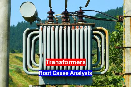
In this post, we will see how to conduct routine tests of transformers.
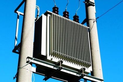
Transformers are an essential part of the electrical circuit. It is a device which is used to change voltage range; either increasing it to a certain level or decreasing it to a certain level.
The transformer is one of the most essential components used in an electrical network. Voltage conversion is necessary because you cannot always apply the same input voltage to any device.
Every instrument has its own set of power requirements and it varies from instrument to instrument. In any case, whether used or unused, the transformer should be ready to perform its function, without failing.
Routine Tests of Transformers
So, before dispatching the transformer from a manufacturer’s premises, it is subjected to various routine tests to see its functionality and whether it is able to survive in abnormal conditions or not. You can simply relate it to a quality test. If the quality of a product is not good before dispatch, then it will be rejected and not allowed to be sold in the market.
Likewise, every product that we use undergoes its respective tests in the factory and a transformer is one of them.
In this post, we will discuss some standard routine tests that are performed on a transformer before it is dispatched from a manufacturer’s factory.
On Load Tap Changing Test
There are applications where a transformer is required to vary its output voltage depending on the requirement. Basically, a transformer provides fixed output voltage depending on the available input. But, we also have a special type called an auto transformer.
Consider a single winding starting from A (primary) and ending with B (secondary). There is a center tap position in between named C. This tap is movable.
The number of turns between A and B is called primary winding and the number of turns between B and C is called secondary winding. As position C is movable, the voltage across the secondary windings will also vary. This is called an autotransformer.
So, a test called on-load tap changing is performed on such types to see how it operates in case of varying demands. The circuit consists of a specific number of taps, with a center tap that will be used as a pointer for the number of turns.
The center tap will be varied and put on a particular tap position, to determine the turns ratio; and accordingly, the output voltage will be checked.
Transformation Ratio Test
This test can be termed an extension of the first test. The role of the transformer as discussed earlier is to provide a required voltage, which will be dependent on the number of turns in primary and secondary.
The turns ratio between them determines the maximum output voltage that will be delivered on the secondary side, depending on the maximum permissible input voltage on the primary side.
The formula for testing output voltage is (secondary voltage / primary voltage) * test voltage.
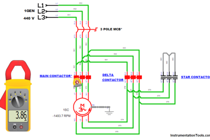
So, suppose the maximum applicable input voltage is 440 V and the maximum possible output voltage is 220 V. Now, you are applying an input voltage (test voltage) of 100 V.
The output voltage in this case according to the formula will be 50 V. This gives a ratio of 0.5 (secondary/primary).
So, every time you apply a particular input voltage, the corresponding output voltage should be the same keeping the ratio in mind.
Make 4-5 tests and get a sample of the ratios, each time a test is performed.
If the ratio matches every time, then it shows that the turn windings of both the primary and secondary are proper and there is no short circuit, insulation loss, resistance loss, etc. between them.
Insulation Resistance Test
Insulation of a transformer must be proper, to ensure that it lives a long life and also does not endanger any person or object surrounding it.
Insulation losses are very grave and can result in damage to the transformer. The insulation resistance is measured between HV and LV windings, between HV windings and earth, and between LV windings and earth.
The values must be noted at regular intervals of 15 seconds, 1 minute, and 10 minutes. This resistance value starts to increase with the duration of the applied voltage.
Then, it is to be noted that a high IR value means the insulation is dry, and that it is a good sign of insulation.
Dielectric Test
This test can be termed an extension of the insulation resistance test. It is used to check the insulation strength properties of the transformer.
It is performed by two tests – a separate source voltage withstand test and an induced voltage test.
In the first test, one winding is supplied with the applied voltage for 60 seconds. The second winding is connected to the earth.
If the dielectric properties are not proper, then insulation loss will occur during this test and you could observe leakage current from it.
In the second test, the primary winding is kept open and the secondary winding is applied with a voltage that is double in amplitude and frequency than its rated voltage.
This voltage will be applied for 60 seconds. During such a full load test, if no breakdown occurs and there is no leakage, then the insulation is proper.
Winding Resistance Test
This test is used to determine I²R losses in transformer and winding temperature. Proper winding resistance means the connections in the windings are tight.
This test is normally performed by four procedures –
- the ammeter voltmeter method,
- Kelvin Bridge method,
- Bridge method, and
- an automatic winding resistance measurement kit.
Vector Group Test
There are applications where multiple transformers are required to be connected in parallel. But, these different connections give different magnitude and phase differences of secondary voltage; there will always be a phase difference.
If this phase sequence and divergence are not equal, then it will not be possible to connect the transformers in parallel; as it would result in winding and insulation losses.
So, to operate the transformers in parallel operation, a vector group test is performed to check whether the phase sequence and divergence are equal or not.
There should not be any leading or lagging of edges, otherwise, the transformers will malfunction.
Vector group calculations are mathematical formulas that make various combinations of phase windings of two transformers and then, the result must be the same for all the equations. Then only, the transformers can be used for parallel operation.
Temperature Rise Test
This test is performed on oil transformers to check the oil temperature and winding temperature. It must be within the specified limits.
In this way, routine tests are performed on transformers to check their operation and performance in all the conditions when it goes on site for actual use.