An Electric Fence Gates is a barrier that uses electric shocks to deter animals and people from crossing a boundary. The voltage of the shock may have effects ranging from discomfort to death.
Where fences surround electrical facilities or areas where a fence could be energized from a fault, either from within the facility or one transferred in from attached fences or other metallic connections, they must be grounded to protect both the worker in the facility and the general public who may touch it from the outside. The normal scheme for grounding the fence is to ground all corner posts and one line post every 50 feet (15 m).
There are two methods used in designing the fence grounding system, especially at an electrical facility:
1. Electrically connect the fence grounding system to the facility ground system (Fig: 1). This method must be used when the fence is within or close to the facility ground grid.

Fig: 1
2. Use a separate grounding system for the fence, isolated from the facility ground system (Fig: 2).

Fig: 2
When the fence is tied to the grid, this increases the grid size which reduces both the grid resistance and the ground grid voltage rise. However, the internal and perimeter gradients must be kept within safe limits because the fence is also at the full potential rise.
This can often be accomplished by burying a perimeter conductor 3 to 4 feet outside the fence and bonding the fence and the perimeter conductor together at frequent intervals (Fig: 3).

Fig: 3
The conductor could be buried under the fence line if one is unable to place it outside. But the touch potential for a person standing one meter outside the fence would be about 60% greater than if the perimeter conductor were buried one meter outside.
With the perimeter conductor one meter outside the fence, a worker standing inside the fence will have an increase in touch potential, but only by about 10%. If the fence is not connected to the main grid (Fig. 2), the following must be considered:
- Could an energized line fall on the fence?
- Could other hazardous potentials exist during other types of faults?
- Can the fence be completely isolated from the main grid at all times, including future expansions?
Fence grounding specifications
Some ground only the fence fabric, others only the fence post. Some continue the conductor up and ground the top rail while others ground the top barbed wire.

The National Electrical Safety Code (NESC), ANSI C2- 1997, states (Rule 92E) that where substation fences are required to be grounded they shall be designed to limit touch, step and transferred voltages in accordance with industry practices.
When the fence posts are constructed of conducting materials the grounding conductor shall be connected to the fence posts with suitable connectors. When the posts are made of a non-conductive material, the fence barbed wire or mesh strands shall be bonded at each grounding conductor point. (Fig. 4)

Fig: 4
The NESC also requires that fences be grounded on each side of a gate or similar opening and the gate shall be bonded to the grounding conductor, jumper or fence.
Manufacturers offers a complete line of factory-made flexible bonding jumpers and clamps for use with just about any fence. In addition, all conductive gates shall be bonded across the opening by a buried conductor. (Fig 5)

Fig: 5
A second conductor, although not required by NESC, offers personnel protection if installed under the swing area of the gates as shown in (Fig. 5). It is also common practice to connect the ground conductor to each corner post and to line posts every 50 feet.
Following are fence and gate grounding details which may be helpful. (Fig. 6, and 7)
Typical construction drawing detail showing fence line and corner post grounding. (Fig: 6)
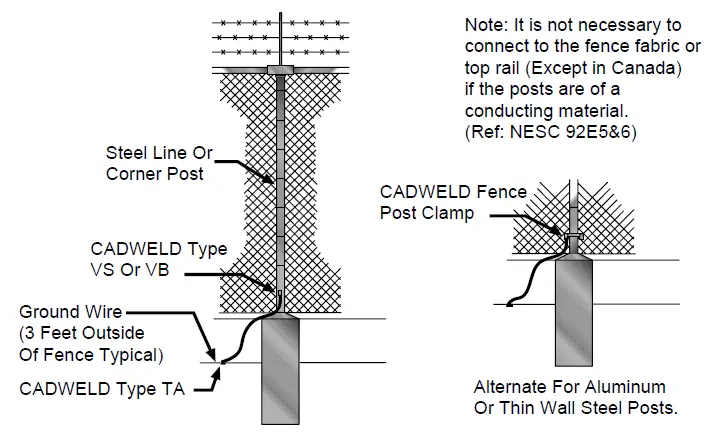
Fig: 6
Typical construction drawing detail showing gate and gate post grounding. (Fig: 7)
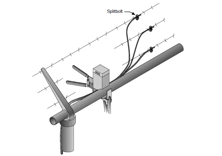
Fig: 7
Various styles of clamps are available for fence post grounding and for gate and gate post bonding and grounding. (Fig. 8)
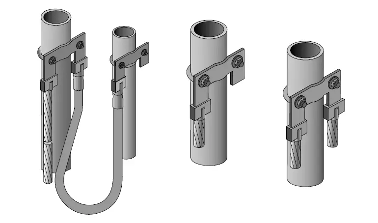
Fig: 8
Various styles of welded connections are available for gate bonding and gate post grounding, including a combination of welds and a clamp where the gate must occasionally be removed. (Fig. 9)
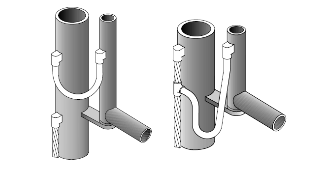
Fig: 9
Standards require that the barbed wire above the fence mesh at a substation to be grounded. Generally recommends that the connections to the barbed wire use split bolt connectors. (Fig. 7)
Fence posts come in a variety of sizes and shapes. (Fig. 10)
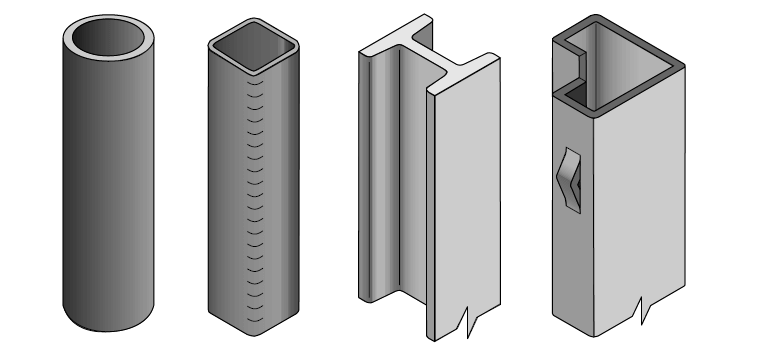
Fig: 10