Inst ToolsInst ToolsInst Tools
  • Courses
  • Automation
    • PLC
    • Control System
    • Safety System
    • Communication
    • Fire & Gas System
  • Instrumentation
    • Design
    • Pressure
    • Temperature
    • Flow
    • Level
    • Vibration
    • Analyzer
    • Control Valve
    • Switch
    • Calibration
    • Erection & Commissioning
  • Interview
    • Instrumentation
    • Electrical
    • Electronics
    • Practical
  • Q&A
    • Instrumentation
    • Control System
    • Electrical
    • Electronics
    • Analog Electronics
    • Digital Electronics
    • Power Electronics
    • Microprocessor
  • Request
Search
  • Books
  • Software
  • Projects
  • Process
  • Tools
  • Basics
  • Formula
  • Power Plant
  • Root Cause Analysis
  • Electrical Basics
  • Animation
  • Standards
  • 4-20 mA Course
  • Siemens PLC Course
Reading: Proper Earthing Practices Used for PLC Control Panel
Share
Notification Show More
Font ResizerAa
Inst ToolsInst Tools
Font ResizerAa
  • Courses
  • Design
  • PLC
  • Interview
  • Control System
Search
  • Courses
  • Automation
    • PLC
    • Control System
    • Safety System
    • Communication
    • Fire & Gas System
  • Instrumentation
    • Design
    • Pressure
    • Temperature
    • Flow
    • Level
    • Vibration
    • Analyzer
    • Control Valve
    • Switch
    • Calibration
    • Erection & Commissioning
  • Interview
    • Instrumentation
    • Electrical
    • Electronics
    • Practical
  • Q&A
    • Instrumentation
    • Control System
    • Electrical
    • Electronics
    • Analog Electronics
    • Digital Electronics
    • Power Electronics
    • Microprocessor
  • Request
Follow US
All rights reserved. Reproduction in whole or in part without written permission is prohibited.
Inst Tools > Blog > PLC Tutorials > Proper Earthing Practices Used for PLC Control Panel

Proper Earthing Practices Used for PLC Control Panel

In this post, we will cover the basic topics on how to follow standard earthing practices used for a PLC control panel.

Last updated: September 28, 2022 4:16 pm
Viral Nagda
PLC Tutorials
2 Comments
Share
7 Min Read
SHARE

In this post, we will cover the basic topics on how to follow standard earthing practices used for a PLC control panel.

Contents
Types of EarthingElectrical EarthingInstrument EarthingIntrinsic Safety EarthingGood Practices of Earthing

We all are familiar with the term earthing in an electrical circuit. Our day-to-day life involves the use of electrical equipments around us and every such equipment has the facility of earthing in it.

In the world of industrial automation, the PLC control panel that we use has the feature of earthing provided in it.

So, here, we will understand what the exact meaning of earthing is and how it must be properly implemented in a PLC control panel.

Every equipment used in a control panel (low power or high power) generates some electrical leakage current or noise during operation.

When it interferes with other equipments around it, it causes abrupt operation and creates disturbances in the circuit. They do not provide the required output & pose threats of electric shocks during fault conditions.

During such conditions, a very high current flows through the circuit and there are chances that it will not flow to it’s designated path, but instead flow through metallic body of machines or panels.

When any person comes in contact with this path, he will be prone to electrical shock. These leakage currents thus pose a threat to the nearby environment. So, it is necessary to divert these currents to some other path. This is done by earthing.

Earthing is the means of passing electrical energy directly to the earth (earth pit) with the help of some non-current carrying part of the equipment or connecting neutral of the supply system to ground.

The leakage or fault current passes to the earth which has zero potential. This nullifies it’s action and protects the nearby environment from damage.

Earthing is checked by measuring the value of ground resistance. It should ideally be between 0-5 ohms. This resistance must be measured periodically to maintain a safe surrounding.

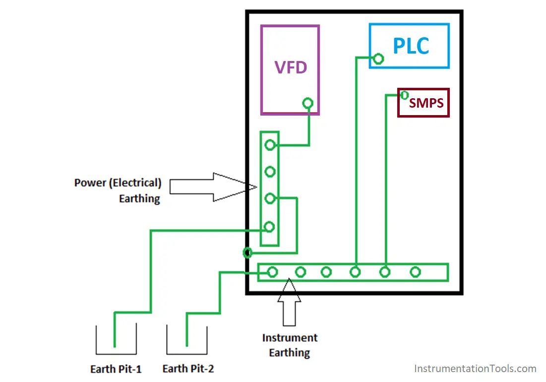
Now, let us focus on the types of earthing and practices generally used for PLC control panel. Look at the below image.

Ideally, let us consider that there are three components in the panel – PLC, SMPS and VFD. The green lines indicate earthing lines. Each equipment has it’s earthing point incorporated in it.

A wire is routed from those corresponding points to the earthing busbar (shown in a green rectangle).

Types of Earthing

There are three types of earthing done in the control/instrumentation panel:

  1. Safety Earth / Electrical Earth / Power Earth
  2. Instrument Earth / Electronic Earth
  3. Intrinsic Safety Earth for IS circuit.
Proper Earthing Practices Used for PLC Control Panel

Electrical Earthing

Power Earthing (also called electrical earthing) is provided to devices that are of high power and generate a large amount of leakage current. Here, the VFD has been given power earthing. The cable used is of a larger size.

The panel body has also been given power earthing by touching a point from the body to the busbar. The panel body is given electrical earthing as all the equipment is attached to it and chances are also that the noise from main incomer power supply will also flow through it.

Instrument Earthing

Instrument Earthing is provided to devices that are of low power and generate a low amount of leakage current. Here, the PLC and SMPS have been given instrument earthing. The cable used is of a smaller size.

Intrinsic Safety Earthing

Intrinsic Safety (IS) Earthing is used for intrinsic safe devices. They are devices that generate a certain amount of thermal and electrical energy which can cause fire or explosion in hazardous areas.

Now, it is to be remembered that all the different earth busbars inside the panel must be isolated from each other and there should not be any connection between them.

This will ensure proper routing of leakage current to its designated earth pits; and thus ensuring a safe working environment. The final conducting cables from the corresponding busbars should be routed to the corresponding earth pits.

Good Practices of Earthing

There are some important points to remember for a good practice.

  • Earth is basically zero potential. But due to neutral connection (from main incomer supply), a small amount of earth to neutral voltage is present. It must not exceed more than 2V. A larger voltage than this indicates that the earthing provided to the panel is not proper and must be rectified at the pit end, along with proper tracing of all the earthing cables from individual control panels and whether they are routed properly or not.
  • An automation panel will obviously have analog / digital instruments and field wiring. They generally use single pair / multi-pair cables with shields. The shield part is to be cut and connected with the earth.
  • Ensure continuity of all the earth cables up to the earth busbar and then up to earth pits.
  • All the field instruments body should also be properly earthed.
  • Avoid the formation of the ground loop inside the electrical panel as ground loop current will have an effect on the performance of field instruments.
  • Proper designing of busbars along with a proper selection of cables used for earthing is the main criteria for a safe environment.

Author: Viral Nagda

If you liked this article, then please subscribe to our YouTube Channel for PLC and SCADA video tutorials.

You can also follow us on Facebook and Twitter to receive daily updates.

Read Next:

  • Good and Bad Wiring Practices
  • Types of Calibration
  • Problem on PLC, HMI, VFD
  • FB Block in Siemens PLC Programming
  • Function Block for Motor Control Logic
Don't Miss Our Updates
Be the first to get exclusive content straight to your email.
We promise not to spam you. You can unsubscribe at any time.
Invalid email address
You've successfully subscribed !

Continue Reading

Standard Colors in PLC Automation Systems
Electrical Switches Principle & Types
Positive and Negative Edges using Statement List Language
Different Types of Schneider PLC
Network Switch Requirement in SCADA and DCS Architecture
PLC Program to Separate Different Size Objects
Share This Article
Facebook Whatsapp Whatsapp LinkedIn Copy Link
Share
2 Comments
  • ali says:
    September 19, 2021 at 3:45 pm

    HI
    can we connect Armor of IS cables to the electrical earth.
    THKS FOR YOUR REPLY

    Reply
    • Nammu says:
      September 19, 2021 at 4:12 pm

      No, You must have separate earth for IS cables.

      Reply

Leave a Reply Cancel reply

Your email address will not be published. Required fields are marked *

Stay Connected

128.3kFollowersLike
69.1kFollowersFollow
210kSubscribersSubscribe
38kFollowersFollow

Categories

Explore More

PLC SCL Program for Marking Machine
Structured Text PLC Programming for Two-Tanks Level Application
Troubleshooting a 4-20mA Current loop
Cars Garage Counter From the Same Door PLC Logic
PLC Program for Automatic Bottle Rejection System
PLC based 4 Way Traffic Light Control System
Workstation Healthiness Checks
Most Asked Questions on SCADA with Answers

Keep Learning

Functional Block Diagram in PLC for Oil and Water Process

Functional Block Diagram in PLC for Oil and Water Process

Studio 5000 Define Program or Operator Control in Functional Block Diagram

Studio 5000: Define Program or Operator Control in Functional Block Diagram

TIA Portal MOVE Instruction

MOVE Instruction in PLC – What You Need to Know?

PLC control 4 machines with 1 button

CX-Programmer Tutorial: 1 Button To Activate 4 Different Machines

Free Download SCADA Softwares

Free SCADA Software Download

Introduction to PLC

#9 PLC Best Practices – Validate indirections

InTouch SCADA Training Course

Free InTouch SCADA Tutorial Course for Beginners

PLC to PLC Communication using S7 Connection

PLC to PLC Communication using S7 Connection PUT & GET Instructions

Learn More

OPC classic introduction

Overview of OPC Communication

Single-beam non-dispersive analyzer

Single-beam Non-dispersive Analyzer

Thermocouple cold junction compensation

Why Thermocouple Reference Junction Compensation Required ?

Fundamental Motion Control Commands

Fundamental Motion Control Commands

Level Transmitter

What is a Bridle?

Capacitance Level Switch Working Principle

Capacitance Level Switch Working Principle

Erratic H2 Flow Rotameter

Erratic H2 Flow Rotameter

Stability and Uniformity of Temperature Bath

Stability and Uniformity of Temperature Bath

Menu

  • About
  • Privacy Policy
  • Copyright

Quick Links

  • Learn PLC
  • Helping Hand
  • Part Time Job

YouTube Subscribe

Follow US
All rights reserved. Reproduction in whole or in part without written permission is prohibited.
Welcome Back!

Sign in to your account

Username or Email Address
Password

Lost your password?