Inst ToolsInst ToolsInst Tools
  • Courses
  • Automation
    • PLC
    • Control System
    • Safety System
    • Communication
    • Fire & Gas System
  • Instrumentation
    • Design
    • Pressure
    • Temperature
    • Flow
    • Level
    • Vibration
    • Analyzer
    • Control Valve
    • Switch
    • Calibration
    • Erection & Commissioning
  • Interview
    • Instrumentation
    • Electrical
    • Electronics
    • Practical
  • Q&A
    • Instrumentation
    • Control System
    • Electrical
    • Electronics
    • Analog Electronics
    • Digital Electronics
    • Power Electronics
    • Microprocessor
  • Request
Search
  • Books
  • Software
  • Projects
  • Process
  • Tools
  • Basics
  • Formula
  • Power Plant
  • Root Cause Analysis
  • Electrical Basics
  • Animation
  • Standards
  • 4-20 mA Course
  • Siemens PLC Course
Reading: What is SAMA Diagram?
Share
Notification Show More
Font ResizerAa
Inst ToolsInst Tools
Font ResizerAa
  • Courses
  • Design
  • PLC
  • Interview
  • Control System
Search
  • Courses
  • Automation
    • PLC
    • Control System
    • Safety System
    • Communication
    • Fire & Gas System
  • Instrumentation
    • Design
    • Pressure
    • Temperature
    • Flow
    • Level
    • Vibration
    • Analyzer
    • Control Valve
    • Switch
    • Calibration
    • Erection & Commissioning
  • Interview
    • Instrumentation
    • Electrical
    • Electronics
    • Practical
  • Q&A
    • Instrumentation
    • Control System
    • Electrical
    • Electronics
    • Analog Electronics
    • Digital Electronics
    • Power Electronics
    • Microprocessor
  • Request
Follow US
All rights reserved. Reproduction in whole or in part without written permission is prohibited.
Inst Tools > Blog > Instrumentation Design > What is SAMA Diagram?

What is SAMA Diagram?

SAMA is an acronym of Scientific Apparatus Makers Association. SAMA diagram sometimes referred to as control functional diagrams.

Last updated: September 28, 2022 2:36 pm
R Jagan Mohan Rao
Instrumentation Design
No Comments
Share
5 Min Read
SHARE

SAMA is an acronym of Scientific Apparatus Makers Association, in some plants, there has been greater adoption of SAMA diagrams which provide more detailed process diagrams which constitute various process symbols.

Contents
SAMA DiagramISA and SAMA DiagramsThree Element Drum Level Control

SAMA drawings are sometimes referred to as “control functional diagrams”.

SAMA symbols are rarely used on P&IDs. Rather, they are generally used to diagram control systems at a detailed functional level. They provide no information about the device’s location or function, nor about the technology used to implement it.

SAMA Diagram

Usually, SAMA symbols show the control system without reference to the processing equipment or piping details. Still, for complex control systems, because they can show greater functionality compared with other documentation formats, they are often preferred for presenting control strategy details in some industries.

Because of the complexity of their control strategies, SAMA symbols are extensively used in the power generation industry. SAMA methods tend to be used for boiler functional diagrams due to the higher level of control-element details and the visualization they provide.

The newer ANSI (American National Standards Institute) symbols have similarities and differences and are used in many industries. The International Society of Automation (ISA) standards are another choice for putting forward control diagrams.

Many manufacturers of control equipment, particularly distributed control systems (DCS), document their library of control algorithms using something similar to SAMA symbology.

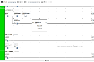
The below figure shows the basic control loop that illustrates SAMA symbols.

Basic control loop with SAMA symbols

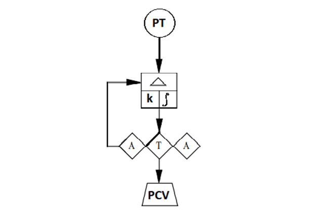
In the above drawing, the three diamonds grouped together represent the adjustable setpoint (left A), the adjustable manual output (right A), the auto/manual transfer switch (T). 

The square-shaped box is a controller. The diamond-shaped enclosures denote that these are all manual functions performed by the operator.

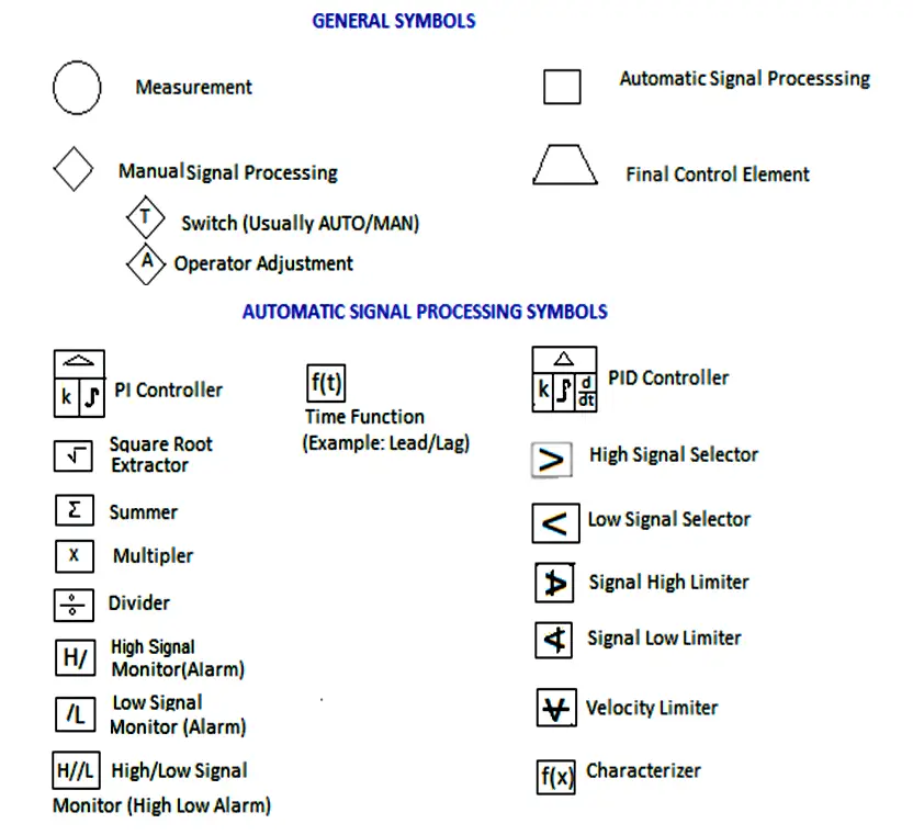
The figure below is an abbreviated list of some of the commonly used symbols.

What is SAMA Diagram

ISA and SAMA Diagrams

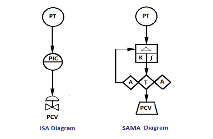
The below figure shows a simplified example using both ISA and its equivalent SAMA functional diagram.

Generally, the ISA symbology tends to be better suited for piping and instrumentation diagrams (P&IDs), while the SAMA diagrams are better suited to indicate complex logic functions and control.

Three Element Drum Level Control

A three-element control loop is an important application in boiler control. Boiler drum level is a critical process variable (PV) in the safe operation of a boiler.

The below figure is a SAMA diagram of the cascade plus feedforward control application approach.

SAMA Example of Three Element Drum Level Control

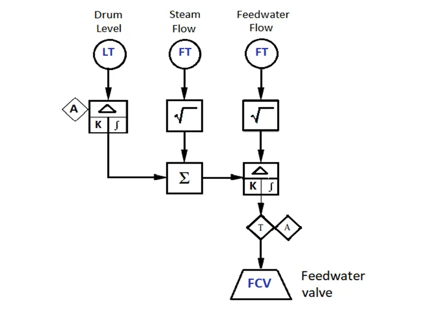
The three transmitters are the three elements referred to in the name of the control system. The feedwater flow setpoint is automatically by the steam flow signal to keep the feed water supply in balance with the steam demand. This is the feed water component of the control methodology.

The drum level controller trims the feedwater flow setpoint to compensate for errors in the flow measurements or any other unmeasured load disturbances such as blowdown that may affect the drum level. This is the cascade component of the control scheme.

The summing function is employed to combine these two components. The square root functions on the flow transmitters linearize the relationship between the flow and differential pressure flow meters.

Interest to read more example and symbols of SAMA? then download the below document.

Title:Functional Diagrams of Instrument and Control Systems
Author:MCAA
Format:PDF
Size:641 KB
Pages:29
Download:Click Here

If you liked this article, then please subscribe to our YouTube Channel for Instrumentation, PLC, and SCADA video tutorials.

You can also follow us on Facebook and Twitter to receive daily updates.

Read Next:

  • Commissioning Documents
  • Documents of PLC or DCS System
  • ISA Codes of Instrumentation
  • As-found and As-left Documents
  • Instrumentation Documents List
Don't Miss Our Updates
Be the first to get exclusive content straight to your email.
We promise not to spam you. You can unsubscribe at any time.
Invalid email address
You've successfully subscribed !

Continue Reading

Why is an Instrument Process Datasheet Required?
What is WHCP?
Design Logic Diagrams with Standard Formats for Process Control
Explain Operation of the Lamp Circuit ?
Control Valve Selection Tips
How to Prepare Pressure Gauge Datasheet ?
Share This Article
Facebook Whatsapp Whatsapp LinkedIn Copy Link
Share
Leave a Comment

Leave a Reply Cancel reply

Your email address will not be published. Required fields are marked *

Stay Connected

128.3kFollowersLike
69.1kFollowersFollow
210kSubscribersSubscribe
38kFollowersFollow

Categories

Explore More

Orifice Flow Meters: Detailed Specifications
Important Factors for Thermocouple Selection
Instrument Protection Methods: Seals
Basic Requirements of Control Valves Sizing
Temperature Gauges and Elements : Detailed Specifications
All About Turbine Meters
Why we use NAMUR Output Sensor?
How to Select a Inductive Proximity Sensor

Keep Learning

Instrumentation Earthing

Instrumentation Earthing

Field Instruments Selection Aid

Field Instruments Selection Aid

Turbine-Compressor System Architecture

Turbine-Compressor System Architecture

Impulse Line Problems

What are Impulse Lines? – Impulse Line Problems & Solutions

Instruments Tapping Points

Instruments Tapping Points – Common versus Individual

Control Valve Recommended Practices

Control Valve Recommended Practices for Harsh Process Conditions

Cable screen shall not be grounded

Cable Screen shall not be Grounded at Field Device ?

Instrument Junction Box Specification

Instrument Junction Box Specification

Learn More

Transmitters 4-20mA Current Failure Alarm Limits

Transmitters 4-20mA Current Failure Alarm Limits

How a Multi Color LED Works

How a Multi Color LED Works ?

high-accuracy voltmeter

Electrical Standards

Siemens Industrial Laptop (Simatic Field PG)

Connect to the Siemens S7 PLC

Types of Script in Intouch Scada

Types of Script in Intouch Scada

Instrumentation Cable trays in Horizontal Installation

Instrumentation Cable trays Installation in vertical orientation

Automatic Transfer Switch

Automatic Transfer Switch (ATS) Using Classic Control Circuit

Servo Tank Gauge Level Principle

Servo Tank Gauges Working Principle

Menu

  • About
  • Privacy Policy
  • Copyright

Quick Links

  • Learn PLC
  • Helping Hand
  • Part Time Job

YouTube Subscribe

Follow US
All rights reserved. Reproduction in whole or in part without written permission is prohibited.
Welcome Back!

Sign in to your account

Username or Email Address
Password

Lost your password?