Inst ToolsInst ToolsInst Tools
  • Courses
  • Automation
    • PLC
    • Control System
    • Safety System
    • Communication
    • Fire & Gas System
  • Instrumentation
    • Design
    • Pressure
    • Temperature
    • Flow
    • Level
    • Vibration
    • Analyzer
    • Control Valve
    • Switch
    • Calibration
    • Erection & Commissioning
  • Interview
    • Instrumentation
    • Electrical
    • Electronics
    • Practical
  • Q&A
    • Instrumentation
    • Control System
    • Electrical
    • Electronics
    • Analog Electronics
    • Digital Electronics
    • Power Electronics
    • Microprocessor
  • Request
Search
  • Books
  • Software
  • Projects
  • Process
  • Tools
  • Basics
  • Formula
  • Power Plant
  • Root Cause Analysis
  • Electrical Basics
  • Animation
  • Standards
  • 4-20 mA Course
  • Siemens PLC Course
Reading: RF Capacitance Level Switch Working Principle
Share
Notification Show More
Font ResizerAa
Inst ToolsInst Tools
Font ResizerAa
  • Courses
  • Design
  • PLC
  • Interview
  • Control System
Search
  • Courses
  • Automation
    • PLC
    • Control System
    • Safety System
    • Communication
    • Fire & Gas System
  • Instrumentation
    • Design
    • Pressure
    • Temperature
    • Flow
    • Level
    • Vibration
    • Analyzer
    • Control Valve
    • Switch
    • Calibration
    • Erection & Commissioning
  • Interview
    • Instrumentation
    • Electrical
    • Electronics
    • Practical
  • Q&A
    • Instrumentation
    • Control System
    • Electrical
    • Electronics
    • Analog Electronics
    • Digital Electronics
    • Power Electronics
    • Microprocessor
  • Request
Follow US
All rights reserved. Reproduction in whole or in part without written permission is prohibited.
Inst Tools > Blog > Level Measurement > RF Capacitance Level Switch Working Principle

RF Capacitance Level Switch Working Principle

Last updated: March 16, 2017 5:28 am
Editorial Staff
Level Measurement Switches
1 Comment
Share
1 Min Read
SHARE

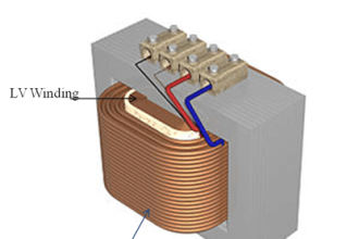
RF-Capacitance /Admittance level switch consists of a guard section, upper insulation, main probe and grounding. The guard section is designed to overcome possible medium attachment and to secure signal accuracy. The special structure is suitable for detecting different mediums without being affected by attachments. The upper main probe, guard, and grounding are all insulated.

The level of the medium can be detected by the increasing of admittance when medium reaches the main probe. The grounding and the main probe are insulated, thus the device will still function accurately and not cause false alarms when the medium attaches the probe.
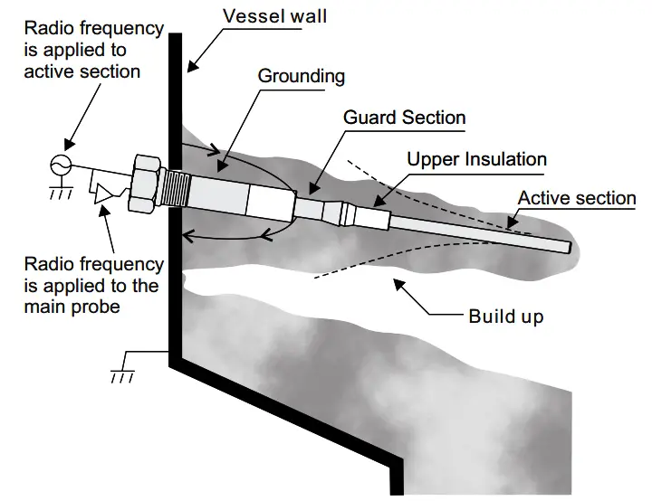
RF-Capacitance Level Switch Principle

Source : FineTek

Don't Miss Our Updates
Be the first to get exclusive content straight to your email.
We promise not to spam you. You can unsubscribe at any time.
Invalid email address
You've successfully subscribed !

Continue Reading

Relay Working Animation
All About Instrumentation Impulse Lines
Radiation based Level Sensor Principle
Ultrasonic Level Switch Principle
Nuclear Level Detectors Cascade or Master/Slave concept
Two Wire Sensor Working Principle and Animation
Share This Article
Facebook Whatsapp Whatsapp LinkedIn Copy Link
Share
1 Comment
  • Green Ibanga says:
    April 24, 2017 at 2:26 pm

    The material is worth learning from.I personally need your compiled book in details for this informations in electrical instrumentation.
    Thanks for considering my humble request.

    Reply

Leave a Reply Cancel reply

Your email address will not be published. Required fields are marked *

Stay Connected

128.3kFollowersLike
69.1kFollowersFollow
210kSubscribersSubscribe
38kFollowersFollow

Categories

Explore More

Interface Level Measurement Selection Guide
Normally-open and Normally-closed Switch Contacts
Capacitive Level Measurement
Installation and Calibration of Level Transmitter
Calibration of Displacer Level Transmitter
Paddle Wheel Level Switch Principle
Open and Closed Tank Level Calculations
Ultrasonic Level Measurement Questions and Answers

Keep Learning

Non‐contact RADAR Level Transmitter Pulse

Non Contact RADAR Level Transmitter Principle, Limitations, Design, Installation and Calibration

Ultrasonic Level Transmitters Installation

Ultrasonic Level Transmitter Principle, Limitations, Calibration and configuration

Practical Level Sensors Questions and Answers

Practical Level Sensors Questions and Answers

Bubbler Level Measurement Animation

Bubbler Level Measurement Animation

Bubble Tube Level measurement

Bubble Tube Level Measurement Principle

Temperature Switch Calibration

How to Calibrate Temperature Switch? – Instrument Basics

Displacer Operated Level Switch Working Principle

Displacer Level Switch Working Principle

Bubbler level measurement

what is a Bubbler System?

Learn More

Pressure Unit Conversion Practical Example

Pressure Unit Conversion Practical Example

Electronic Devices & Circuits Objective Questions

Electronic Devices & Circuits Quiz – Set 3

Historical Scada graph

Configuration of InTouch Scada Trends

Battery Interview QuBattery Interview Question and Answersestion and Answers

Battery Interview Question and Answers

What is Blowdown Valve (BDV)

What is Blowdown Valve (BDV)?

Flow Transmitters Questions and Answers

Flow Transmitters Questions and Answers – Instruments Test

PLC Program for Conveyor Motor

PLC Conveyor Motor Ladder Logic

Functions of Temperature Detectors

Functions of Temperature Detectors

Menu

  • About
  • Privacy Policy
  • Copyright

Quick Links

  • Learn PLC
  • Helping Hand
  • Part Time Job

YouTube Subscribe

Follow US
All rights reserved. Reproduction in whole or in part without written permission is prohibited.
Welcome Back!

Sign in to your account

Username or Email Address
Password

Lost your password?