Inst ToolsInst ToolsInst Tools
  • Courses
  • Videos
  • Q & A
    • Interview
      • Instrumentation
      • Electronics
      • Electrical
      • Practical Questions
    • MCQ
      • Instrumentation MCQ
      • Electrical MCQ
      • Electronics MCQ
      • Control Systems MCQ
      • Analog Electronics MCQ
      • Digital Electronics MCQ
      • Power Electronics MCQ
      • Microprocessor MCQ
      • Multiple Choice Questions
  • EE
    • Electronics
      • Electronics Q & A
      • Electronic Basics
      • Electronic Devices & Circuits
      • Electronics Animation
      • Digital Electronics
    • Electrical
      • Electrical Basics
      • Electrical Q & A
      • Power Electronics
      • Electrical Machines
      • Electrical Animation
      • Power Systems
      • Switchgear & Protection
      • Transmission & Distribution
  • Measure
    • Control Valves
    • Calibration
    • Temperature
    • Pressure
    • Flow
    • Level
    • Analyzers
    • Switches
    • Vibration
    • Solenoid Valve
  • Control
    • PLC Tutorials
    • Control Systems
    • Safety Instrumented System (SIS)
    • Communication
    • Fire & Gas System
  • More
    • Design
    • Tools
    • Animation
    • Basics
    • Formulas
    • Standards
    • TextBooks
    • Common
    • Software
    • Excel Tools
    • Erection & Commissioning
    • Process Fundamentals
    • Videos
    • Books
Search
All rights reserved. Reproduction in whole or in part without written permission is prohibited.
Reading: Shutdown Motors in Timed Operation PLC Program
Share
Notification Show More
Font ResizerAa
Inst ToolsInst Tools
Font ResizerAa
  • Courses
  • PLC Tutorials
  • Control Systems
Search
  • Courses
  • Videos
  • Q & A
    • Interview
    • MCQ
  • EE
    • Electronics
    • Electrical
  • Measure
    • Control Valves
    • Calibration
    • Temperature
    • Pressure
    • Flow
    • Level
    • Analyzers
    • Switches
    • Vibration
    • Solenoid Valve
  • Control
    • PLC Tutorials
    • Control Systems
    • Safety Instrumented System (SIS)
    • Communication
    • Fire & Gas System
  • More
    • Design
    • Tools
    • Animation
    • Basics
    • Formulas
    • Standards
    • TextBooks
    • Common
    • Software
    • Excel Tools
    • Erection & Commissioning
    • Process Fundamentals
    • Videos
    • Books
Follow US
All rights reserved. Reproduction in whole or in part without written permission is prohibited.
Inst Tools > Blog > PLC Tutorials > Shutdown Motors in Timed Operation PLC Program

Shutdown Motors in Timed Operation PLC Program

Write a PLC program to start three motors at the same time and shutdown the motors in a timed sequence operation using ladder logic.

Last updated: March 4, 2021 11:27 am
Editorial Staff
PLC Tutorials
No Comments
Share
4 Min Read
SHARE

Write a PLC program that when a start push button is pressed all the 3 motors are ON and after 3 seconds the first motor shutdowns automatically, then after 7 seconds the second motor shutdowns automatically, and after 12 seconds the last motor shutdowns automatically. At any time if the stop pushbutton is pressed all the three motors are shutdown.

Contents
Inputs and Outputs Shutdown Motors in Timed OperationS_PEXT InstructionPLC Program description Network 1:Network 2:Network 3:

Note the best practice to learn the PLC programming is to start writing the PLC program, take your time before you review the answer.

Inputs and Outputs 

I0.0: start push Button (Normally open contact)

I0.1: Stop Push Button (Normally Closed Contact)

Q0.0: Motor 01

Q0.1: Motor 02

Q0.2: Motor 03

T1: Timer 01

T2: Timer 02

T3: Timer 03

Shutdown Motors in Timed Operation
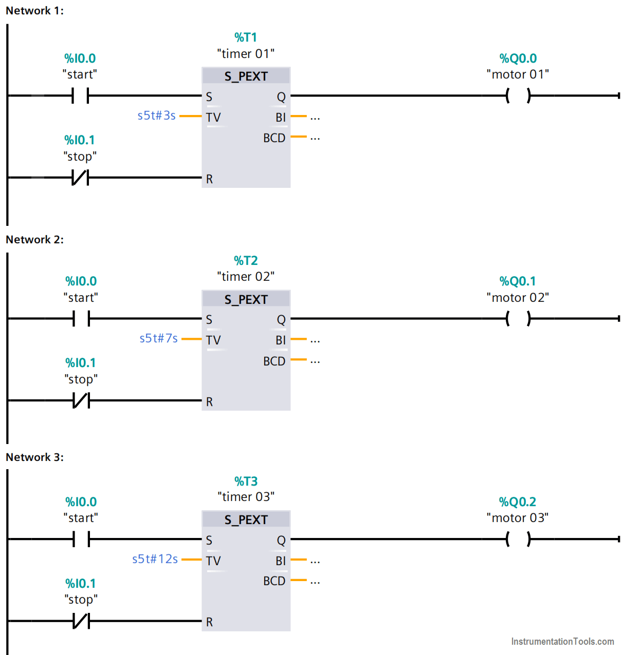
Shutdown Motors in Timed Operation PLC Program

S_PEXT Instruction

S_PEXT (Extended Pulse S5 Timer) starts the specified timer if there is a positive edge at the start (S) input. A signal change is always necessary in order to enable a timer.
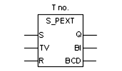
S_PEXT timer block

The timer runs for the preset time interval specified at input TV even if the signal state at the S input changes to “0” before the time interval has elapsed. The signal state at output Q is “1” as long as the timer is running.

The timer will be restarted (“re-triggered”) with the preset time value if the signal state at input S changes from “0” to “1” while the timer is running.

The timer is reset if the reset (R) input changes from “0” to “1” while the timer is running. The current time and the time base are set to zero.

PLC Program description

 Network 1:

  • When the start PB is pressed the “timer 01” is energized and starts to count 3 seconds and runs the “motor 01” for 3 seconds.
  • The PEXT is used because the start signal is a pulse as it is a push-button (PB).
  • When the stop PB is pressed at any time the timer 01 resets and shutdowns the motor 01.

Note: When we press the Start pushbutton for the first time, then all the motors will be turned ON and runs. In the next networks, I am discussing what will happens for the first time when we press the start push-button.

Network 2:

  • When the start PB has pressed the timer 02 is energized and starts to count 7 seconds and runs the “motor 02” for a 7seconds.
  • When the stop PB is pressed at any time the “timer 02” resets and shutdowns the motor 02.

Network 3:

  • When the start PB is pressed the timer 03 is energized and starts to count 12 seconds and runs the “motor 03” for a 12seconds time.
  • When the stop PB is pressed at any time the timer 03 resets and shutdowns the motor 03.

Note: For our simple example, we used motors shutdown time in seconds. In practical industrial applications, it will be in hours, minutes, and seconds depends on our requirements.

Author: Karim Ali Anwar

If you liked this article, then please subscribe to our YouTube Channel for PLC and SCADA video tutorials.

You can also follow us on Facebook and Twitter to receive daily updates.

Read Next:

  • Motor Speed Control
  • Motor Clockwise Operation
  • What is Auto-closing?
  • Siemens Memory Cards
  • Online & Offline Logics
Don't Miss Our Updates
Be the first to get exclusive content straight to your email.
We promise not to spam you. You can unsubscribe at any time.
Invalid email address
You've successfully subscribed !

Continue Reading

Feedback Monitoring in Safety PLC
PLC Digital Signals Wiring Techniques
PLC Program for Alternate Output Circuit with Latched Function
Different Types of Schneider PLC
Compare Servo Motor and Stepper Motor
Data Handling Instructions in PLC Programming
Share This Article
Facebook Whatsapp Whatsapp LinkedIn Copy Link
Share
Leave a Comment

Leave a Reply Cancel reply

Your email address will not be published. Required fields are marked *

Stay Connected

128.3kFollowersLike
69.1kFollowersFollow
208kSubscribersSubscribe
38kFollowersFollow

Categories

Explore More

Free Download Programmable Logic Controller (PLC) Book
Various Control Methods in Servo Motor Drives
PLC Program to Read Temperature in PLC
Introducing PLC Programming using LogixPro Simulator Software
Data Types in PLC – Bit, Byte, Integer, Real, String
Ladder Logic Vs. Other Programming Languages – PLC Basics
Toggle Switch & Sensor: Conveyor and Puncher PLC Program
Difference between Signal Cables and Control Cables
Basic Concepts of the Safety Relay
Open Source PLC and SCADA Software

Keep Learning

PLC Program using START & STOP Buttons

PLC Program using START and STOP Buttons

Database for each safety module

Global Acknowledgment Instruction in Safety PLC

PLC program for Latching and unlatched circuit

PLC Program for Latching and unlatching Circuit

Simple Conveyor Control PLC Program

XG5000 Example of Simple Conveyor Control PLC Program

Difference between Power Cables and Signal Cables

Difference between Power Cables and Signal Cables

V1000 Family Programming Simulator Tool

VFD Simulator Download – Free Yaskawa V1000 Software

Sourcing output module in PLC

Which Connection is Best for PLC? – Sinking or Sourcing

Architecture of Allen Bradley PLC

Architecture of Allen Bradley PLC

Discover More

Working of Shuttle valve

What is a Shuttle Valve? Principle, Advantages, Disadvantages

phototransistor symbols

Phototransistor Working Principle

Coriolis mass flowmeter Density Measurement

How Coriolis Mass Flow Meter Measure Density?

Pressure gauge mechanism

How Measurement Span of Pressure Gauge Could be Changed?

illumination Multiple Choice Questions and Answers

illumination Multiple Choice Questions and Answers (MCQ)

100 Electronics and Electrical Projects for Engineering Students

100 Electronics and Electrical Projects for Engineering Students

Chlorine dioxide measurement principle

Chlorine dioxide Analyzer Principle

Safety Instrumented Systems are different from Basic Process Control Systems

Safety Instrumented System Handbook – SIS Tutorials

Follow US
All rights reserved. Reproduction in whole or in part without written permission is prohibited.
Welcome Back!

Sign in to your account

Username or Email Address
Password

Lost your password?