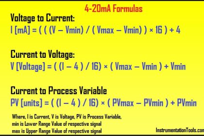
OPEN TANK CAPILLARY REMOTE SEAL LEVEL TRANSMITTERS
1. Transmitter installed exactly at HP tapping point – Open Tank

Tank span = Lmax x SG
Tank Span: (108 in. x 0.75) = 81 inH2O
4 mA = Lmin x SG + Hd x Sg
=(0 x 0.75) + (0 in x 0.934)= 0 inH2O
4mA = 0 inH2O
20 mA = Lmax x SG + Hd x 0.934
=(108in x 0.75) + (0)= 81 inH2O
20mA = 81 inH2O
2.Transmitter installed below HP tapping point – Open Tank

Tank span = (Lmax x SG)
Tank Span: 108in x 0.75 = 81inH2O
Lmin
4 mA = Lmin x SG + (Hd x Sg)
= (0 x 0.75) + (60in x 0.934)
= 56.04 inH2O
Lmax
20 mA = L max x SG + (Hd x Sg)
=(108in x 0.75) + (56.04)
= 137.04 inH2O
SPAN = 81inH2O (137.04 – 56.04)
3.Transmitter installed above the HP tapping Point – Open Tank

Tank span = (Lmax x SG)
Tank Span: 108in X 0.75 = 81inH2O
4mA = Lmin x SG + (Hd x Sg)
= (0 x 0.75) + (120 in. x 0.934) = -112.08 inH2O
NOTE Pressure pulling down on the high sensor side will register as a negative pressure value.
20mA = Lmax x SG + (Ld X 0.934)
= (108 in. x 0.75) + (-112.08) = -31.08 inH2O
SPAN = 81 inH2O (-112.08 to -31.08 inH2O)
CLOSED TANK CAPILLARY REMOTE SEAL LEVEL TRANSMITTERS
Example A :
Transmitter installed exactly at HP tapping point – Closed Tank

Tank span = (Lmax x SG)
Tank Span: 108in X 0.75 = 81inH2O
4mA = Lmin x SG + (Ld x Sg)
= (0 x 0.75) + (120 in. x 0.934) = -112.08 inH2O
20mA = Lmax x SG + (Ld X 0.934)
= (108 in. x 0.75) + (-112.08) = -31.08 inH2O
SPAN = 81 inH2O (-112.08 to -31.08 inH2O)
NOTE Pressure applied to Low sensor side sensor will register as a negative digital value.
Example B :
Transmitter installed above HP tapping point – Closed Tank

Tank span = (Lmax x SG)
Tank Span: 108in X 0.75 = 81inH2O
4mA = Lmin x SG + (Ld x Sg) + (Hd x Sg)
= (0 x 0.75) + (60 in. x 0.934) + (60 in. x 0.934) = -112.08 inH2O
20mA = Lmax x SG + (Ld X 0.934) + (Hd X 0.934)
= (108 in. x 0.75) + (60 in. x 0.934) + (60 in. x 0.934) = -31.08 inH2O
SPAN = 81 inH2O (-112.08 to -31.08 inH2O)
NOTE: Pressure (Ld) is applied to Low sensor side and will register as a negative digital pressure. Pressure (Hd) is pulling down on the high sensor side therefore would also register as a negative digital pressure therefore these values are additive.
Example C :
Transmitter installed below HP tapping point – Closed Tank

Tank span = (Lmax x SG)
Tank Span: 108in X 0.75 = 81inH2O
4mA = Lmin x SG + (Hd x Sg) + (Ld x Sg)
= (0 x 0.75) + (60 in. x 0.934) + (180 in. x 0.934) = -112.08 inH2O
20mA = Lmax x SG + (Hd X 0.934) + (Ld X 0.934)
= (108 in. x 0.75) + (-112.08) = -31.08 inH2O
SPAN = 81 inH2O (-112.08 to -31.08 inH2O)
Pressure (Ld) is applied to Low sensor side and will register as a negative digital pressure. Pressure (Hd) is pulling down on the high sensor side therefore would also register as a negative digital pressure therefore these values are additive.
NOTE: The transmitter location in a closed tank does not effect the 4mA and 20mA set points as shown in example A, B & C.
Abbreviations:
Lmin = the minimum level of process and typically the 4mA lower range value
Lmax = the maximum level of process and typically the 20mA upper range value
Atm = Atmospheric pressure (vented tank)
SG = Specific gravity of the process
Sg = Specific gravity of the remote fill fluid
Hd = Capillary vertical distance from process to high side sensor
Ld= Capillary vertical distance going to low side sensor
Source : Emerson
Articles You May Like :
Diaphragm Seal capillary tube type
DP Level Transmitters Techniques
Potentiometric Level Principle
Optical Level Switch Principle


In the example A transmitter installed exactly at the HP tapping point closed tank i didn’t get where do you find that Hd=60 and Ld = 180 ? Because you have Ld =120in Thank you.
Hello, Thank you for identifying the issue. Now updated the answer. Plz Check.
thanks for the answer
I learnd a lot. thank you
In the first example for calculating 20ma(Tx installed exactly at hp tapping point)given equation is Lmin instead of Lmax
Yes. Updated. Please Check. Thanks
I am facing one problem, also I am new to this plant.
This Level Transmitter was not functioning for 7/8 years since plant running as per operation.
I took up the challenge and installed a new remote diaphragm seal type transmitter.
I had put following values as LRV and URV.
LRV: -1620
URV: -216
C to C distance is 1530mm. Specific gravity of The Liquid Vacuum Residue: 0.9.
At zero conditions i.e. both upper and lower root isolation valves closed, Diaphragm spacer rings drain and Vent caps opened , then I found PV: -1620 which I had entered as LRV.
For URV, -1620+ (1530x 0.9)= -216 .
Level Transmitter service is vacuum column slop distillate, Column pressure is -676mmHg. i.e. -9190mmWC.
As I have not considered the vacuum factor for above calculation so I have doubt on my LRV and URV values.
Kindly enlighten me about how to calculate LRV and URV values and how and where to consider the vacuum pressure factor in my calculation.
Regards
Dhrubajyoti Borah
Numaligarh Refinery Limited.
Assam
Everywhere in the calculation, you have mentioned HP-LP as HP+LP.
Please correct me if I am wrong.
Hello, All calculations looks fine. Please re-check. if anything is there then plz explain clearly. Thank you.
D/Sir,
Pl send your contact details .
You can contact me on InstrumentationTools@gmail.com
Transmitter installed above HP tapping point – Closed Tank
Your equation for 4ma:
= (0 x 0.75) + (60 in. x 0.934) + (60 in. x 0.934) = -112.08 inH2O
can not equal -112.08, actually comes out to 112.08.
= (0 x 0.75) – (60 in. x 0.934) + (-60 in. x 0.934) = -112.08 inH2O
where HD = -60 in. because it is below transmitter. I think some of your other equations may have same issue. Otherwise, thanks for the info, great job.
bharadwaj sir you are simply awesome ,,keep going
Hello Sir,
How Can I Find SG & Sg
Hi, Know your liquid in the tank/vessel/LP Impulse Line. Click Here for Values
Sir..
How can I calculate LRV URV of a capillary pressure transmitter mounted on top of the process pipe line…..
Transmitter mounted 1 meter downward from the flange….
I wonder if leveling with a remote seal How will the effect differ when measuring using zero press and using drop zero?
Calculation shown on eg. 3B is in-correct, HP side we shall not consider SG, i.e. no pressure on HP side if Tx. is above HP tap.
Transmitter installed below the HP tapping point
From example 3 B:
It is mentioned both Ld and Hd pressure register negative digital pressure . according this mentioned the value will be -224.16 inH2O
But it is given as below
4mA = Lmin x SG + (Hd x Sg) + (Ld x Sg)
= (0 x 0.75) + (60 in. x 0.934) + (180 in. x 0.934) = -112.08 inH2O
Please explain
Hello,
I have a condition where I need to install a remote seal DPT for a closed vessel’s level measurement where the application is slurry.
Problem is, I must put a “continuous flushing” of hot water at HP side of the transmitter, in order to not to allow process fluid to choke. This continuous flushing fluid will always exert pressure on the HP side.
So, the question is how to nullify this pressure or DP (between fluid pressure & vessel pressure) in calculating the range?
Please advise.
Thanks in advance,
Jitesh Kansara