Control system architecture can range from simple local control to highly redundant distributed control systems. Reliability criteria for industrial facilities dictate the application of redundant or distributed control systems or programmable logic controllers.
Local Control System Architecture
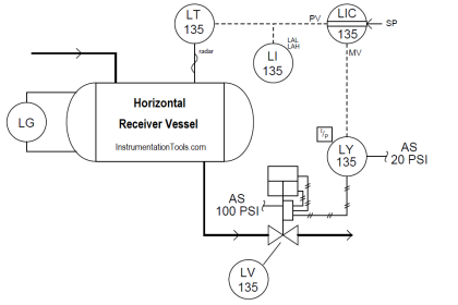
The below Figure describes a system architecture in which sensors, controller, and controlled equipment are within close proximity and the scope of each controller is limited to a specific system or subsystem.

Local controllers are typically capable of accepting inputs from a supervisory controller to initiate or terminate locally-controlled automatic sequences, or to adjust control setpoints, but the control action itself is determined in the local controller.
Required operator interfaces and displays are also local. This provides a significant advantage for an operator troubleshooting a problem with the system, but requires the operator to move around the facility to monitor systems or respond to system contingencies.
Examples of local control are the packaged control panels furnished with chillers or skid-mounted pump packages.
Centralized Control System
Centralized control describes a system in which all sensors, actuators, and other equipment within the facility are connected to a single controller or group of controllers located in a common control room. Locating all controls, operator interfaces and indicators in a single control room improves operator knowledge of system conditions and speeds response to contingencies.
This type of system architecture was common for power plants and other facilities using single-loop controllers or early digital controls in the past, but it has now been largely supplanted by distributed control because of the high cost associated with routing and installing all control system wiring to a central location.

Centralized control systems should only be considered for small industrial facilities and if used, must have fully redundant processors. Where redundancy is provided in a centralized control system segregated wiring pathways must be provided to assure that control signals to and from equipment or systems that are redundant are not subject to common failure from electrical fault, physical or environmental threats.
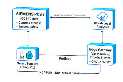
Distributed Control System
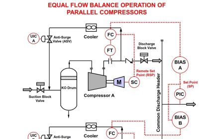
Distributed control system architecture offers the best features of both local control and centralized control. In a distributed control system, controllers are provided locally to systems or groups of equipment, but networked to one or more operator stations in a central location through a digital communication circuit.

Note : The above Architecture is an simplified example of DCS. Real-time system may vary as per requirements.
Control action for each system or subsystem takes place in the local controller, but the central operator station has complete visibility of the status of all systems and the input and output data in each controller, as well as the ability to intervene in the control logic of the local controllers if necessary.
Advantages of Distributed Control Systems
There are a number of characteristics of distributed control architecture which enhance reliability:
- Input and output wiring runs are short and less vulnerable to physical disruption or electromagnetic interference.
- A catastrophic environmental failure in one area of the facility will not affect controllers or wiring located in another area.
- Each local controller can function on its own upon loss of communication with the central controller.
Limitations of Distributed Control Systems
There are also specific threats introduced by distributed control architecture that must be addressed in the design of the system:
- Networks used for communication may become electronically compromised from outside the facility.
- Interconnection of controllers in different locations can produce ground loop and surge voltage problems.
- If the central controller is provided with the ability to directly drive the output of local controllers for purposes of operator intervention, software glitches in the central controller have the potential to affect multiple local controllers, compromising system redundancy.
- Distributed control system architecture redundancy must mirror the redundancy designed into the mechanical and electrical systems of the facility. Where redundant mechanical or electrical systems are provided, they should be provided with dedicated controllers, such that failure of a single controller cannot affect more than one system. Equipment or systems that are common to multiple redundant subsystems or pathways, (such as generator paralleling switchgear) should be provided with redundant controllers.
Reference : This material adapted from the “Department of the Army, TM 5-601, Supervisory Control and Data Acquisition (SCADA) Systems for Command, Control, Communications, Computer, Intelligence, Surveillance, and Reconnaissance (C4ISR) Facilities, 21 January 2006.”
Articles You May Like :
Process Safety Instrumentation