Magnetostrictive Level Transmitter is a two wire loop powered instrument which transmits an analog 4-20mA loop current in proportion to the measured liquid level in the tank.
This type of level transmitter uses a special type of sensor probe with a magnetic float to sense the level. The float is selected such that it’s specific gravity is lighter than the liquid whose level is to be measured, so that it always floats on the liquid.
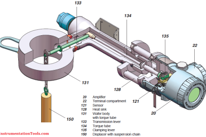
Magnetostrictive Instrument
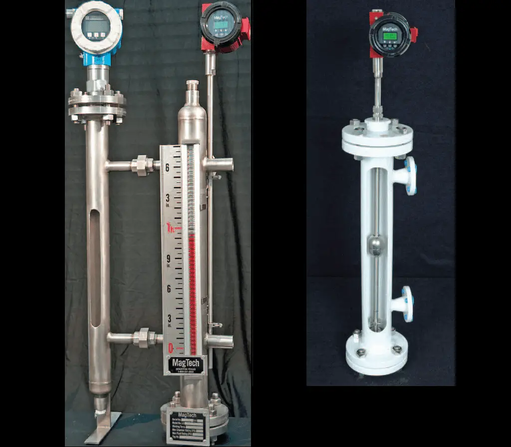
Image Courtesy: ekotech
This sensor probe with magnetic float is inserted into a tank or briddle where the liquid level to be measured. The float raises or falls as per the liquid level in the tank.
This level transmitter operation is based on the principle of magnetostrictive technology.
The transmitter generates a high-current pulse and transmitted down to the sensor probe, this is called as wave guide. This wave guide produces a circular magnetic field around the sensor probe (wire). The float also carries a permanent magnet in it.
When this wave guide reaches the permanent magnet in the float, a torsional force is produced, twisting the wire and producing a torsional wave (shown in below figure). This torsional wave travels back to the transmitter. By measuring the time of flight of the torsional wave (time duration), we can easily calculate the tank level.
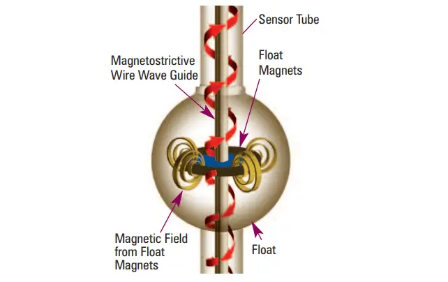
Image Courtesy: ekotech
As the tank level changes, the float tracks the change and continuously activates the sensor in the tube. The electronics in the transmitter process the changing signal and generates an 4-20 mA output corresponds to the measured level.
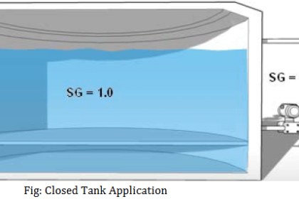
The Magnetostrictive Level Transmitter can also be used to measure the interface level between two fluids.
Calibration
The Magnetostrictive Level Transmitter calibration carried out using two ways.
- Using Push buttons on the transmitter
- Using HART Communicator
Calibration using Pushbuttons
Setting the 4mA or LRV
- Move the float to the desired 0% level reference.
- Enter the calibration mode by pressing the UP & DOWN buttons.
- Go to the Zero trim using the push buttons and set the output at 4.00mA.
Setting the 20mA or URV
- Move the float to the desired 100% level reference.
- Enter the calibration mode by pressing the UP & DOWN buttons.
- Go to the Span trim using the push buttons and set the output at 20.00mA.
Note: The push buttons sequence may vary from manufacturer to manufacturer, refer the technical manual.
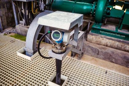
Gauge Mounted Magnetostrictive Level Transmitter Calibration
In this case, both level gauge and level transmitter are mounted on the same unit.
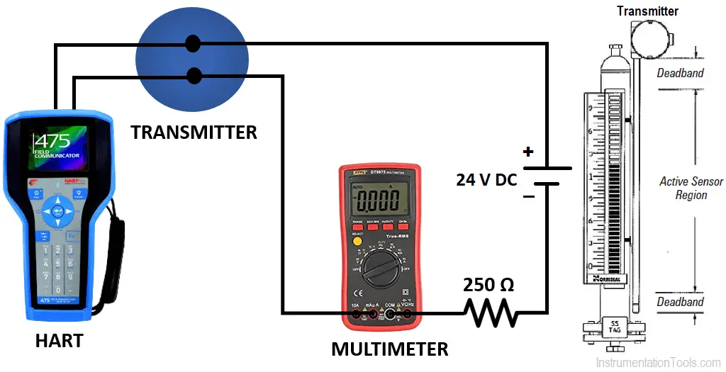
- Connect the magnetostrictive level transmitter as shown in the above image.
- Take the datasheet of the particular level transmitter. In the datasheet, you will find lower range value (4mA) and upper range value (20mA). Example: LRV is 5 inch and URV is 20 inch. If you don’t have the datasheet then manually measure the length using the tape.
- Level gauge and transmitter is mounted on the same unit, you can use the level guage readings as reference during level chamber filling.
- Now fill the level chamber with the water upto the 0% reference level and read the transmitter readings using the HART communicator.
- Transmitter has to show 0% level, if not then do zero trim using the HART communicator.
- Now fill the level chamber with the water upto the 100% reference level and read the transmitter readings using the HART communicator.
- Transmitter has to show 100% level, if not then do span trim using the HART communicator.
- During the calibration, multimeter may be used to note down the corresponding loop current.
Note: We can also use the same process liquid instead of water for the calibration, if it is not hazardous.
Direct Mount Magnetostrictive Level Transmitter Calibration
In this case, there is no level gauge available.
- Connect the magnetostrictive level transmitter as shown in the above image.
- Take the datasheet of the particular level transmitter. In the datasheet, you will find lower range value (4mA) and upper range value (20mA). Example: LRV is 5 inch and URV is 20 inch. If you don’t have the datasheet then manually measure the length using the tape.
- Move the float to the 0% reference level and read the transmitter readings using the HART communicator.
- Transmitter has to show 0% level, if not then do zero trim using the HART communicator.
- Move the float to the 100% reference level and read the transmitter readings using the HART communicator.
- Transmitter has to show 100% level, if not then do span trim using the HART communicator.
- During the calibration, multimeter may be used to note down the corresponding loop current.
Note:
The float was designed to operate at a specific gravity of process medium which will be there in the tank. During our calibration, if we use water for the float movement, then there will be some error when the transmitter taken inline. As the process medium and water have different specific gravities.
The error may be positive or negative as it depends on your float specifications. It is recommended to use a attached level guage reading for making the reference 0% and 100% level. In case if there is no attached level guage then it is best to disassemble the unit and manually move the float to 0% and 100% during the calibration.
Read Next
- Calibration of Displacer Level Transmitter
- Pressure based Level Transmitter Errors
- Open Tank DP Level Transmitter Calculation


Hi ! Could you please supply me ( with proper schematic diagrams ) the working principles of (1) a current to pneumatic converter which is used on ships (2) electric telegraph – also how the wrong way alarm functions .
I have already read the book on Instrumentation and Control by G J Roy but am still unable to understand properly .Pls help. Thanks and best regards.
Ashok K. Srivastava
what is the manufacturer recommended storage condition or procedure if not installing immediately short term/long term preservation
Magneto strictive Level Transmitter continuously fluctuating from 4 to 20,Please let me know how to resolve this issue.
However, verified all parameters and also calibration done successfully.
Could you please advise.
Magneto strictive level transmitter has its own limitation to process signal and give relevant output signal in the area between 100% to 82% of a filled tank level. So, in order to get stable reading, tank should not be filled above 82% of its level.