Inst ToolsInst ToolsInst Tools
  • Courses
  • Automation
    • PLC
    • Control System
    • Safety System
    • Communication
    • Fire & Gas System
  • Instrumentation
    • Design
    • Pressure
    • Temperature
    • Flow
    • Level
    • Vibration
    • Analyzer
    • Control Valve
    • Switch
    • Calibration
    • Erection & Commissioning
  • Interview
    • Instrumentation
    • Electrical
    • Electronics
    • Practical
  • Q&A
    • Instrumentation
    • Control System
    • Electrical
    • Electronics
    • Analog Electronics
    • Digital Electronics
    • Power Electronics
    • Microprocessor
Search
  • Books
  • Software
  • Projects
  • Process
  • Tools
  • Basics
  • Formula
  • Power Plant
  • Root Cause Analysis
  • Electrical Basics
  • Animation
  • Standards
  • 4-20 mA Course
  • Siemens PLC Course
Reading: How to Measure Density using DP Transmitter?
Share
Notification Show More
Font ResizerAa
Inst ToolsInst Tools
Font ResizerAa
  • Courses
  • Design
  • PLC
  • Interview
  • Control System
Search
  • Courses
  • Automation
    • PLC
    • Control System
    • Safety System
    • Communication
    • Fire & Gas System
  • Instrumentation
    • Design
    • Pressure
    • Temperature
    • Flow
    • Level
    • Vibration
    • Analyzer
    • Control Valve
    • Switch
    • Calibration
    • Erection & Commissioning
  • Interview
    • Instrumentation
    • Electrical
    • Electronics
    • Practical
  • Q&A
    • Instrumentation
    • Control System
    • Electrical
    • Electronics
    • Analog Electronics
    • Digital Electronics
    • Power Electronics
    • Microprocessor
Follow US
All rights reserved. Reproduction in whole or in part without written permission is prohibited.
Inst Tools > Blog > Density Measurement > How to Measure Density using DP Transmitter?

How to Measure Density using DP Transmitter?

Last updated: November 27, 2019 11:47 am
Editorial Staff
Density Measurement Level Measurement
No Comments
Share
2 Min Read
SHARE

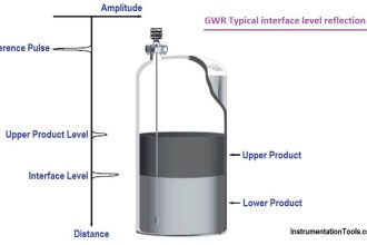
For Density measurement using DP transmitter, the height of the tank is kept constant then Change in Pressure is due to Change in Density.

Contents
Density Calculation​ Using DP TransmitterOur Calibration range is 50 inH2O to 90 inH2O

First Let’s Understand the concept

The calculation is very similar to Normal level calculation

Density Calculation​ Using DP Transmitter

Here’s our simple pressure measurement formula.

Density Calculation​ Using DP Transmitter

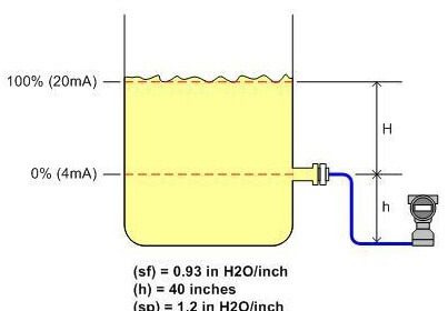
The Pic above shows a Container of Height 100 Inches

And this tank contains Liquid of Specific gravity 0.5

So what is the pressure at the bottom?

Height x Specific gravity= InH2O ……..(Reference below)

100 (inches) X 0.5 = 50 inH2O

Now let’s keep the “Height Same” and Change specific Gravity to 0.9

Height x Specific gravity= InH2O

100 (inches) X 0.9 = 90 inH2O

How to Measure Density using DP Transmitter

So if Height is kept CONSTANT then change in pressure is just due to CHANGE IN DENSITY (Specific gravity)

When the Transmitter feels the pressure of 50inH2O we get to know the S.G of liquid inside is 0.5

And, When Transmitter feels the pressure of 90inH2O we get to know the S.G of liquid inside is 0.9

If this Concept is clear the calculation is “Piece of Cake” !!!

Our Calibration range is 50 inH2O to 90 inH2O

Here are the steps in a simplified manner

For 4mA Cases (LRV – Lower Range value case)

1) Calculate the Pressure at LP side (tapping) of Transmitter

2) Calculate the Pressure at HP side (tapping) of Transmitter

3)Differential pressure = Pressure at (HP Side – LP Side)

Repeat the same for 20mA case (URV – Upper Range value case)

Reference:-

Refer Simple Level calculation article for reference as to how to execute the above steps

  1. Simple DP Level Calculation
  2. Interface Level Calculation

Thanks for Reading !!

Author: Asad Shaikh

Profile: Linkedin

Read Also:

  • Dry Leg & Wet Leg Calculation
  • Suppression and Elevation
  • Open Tank Level Measurement
  • Closed tank Density Measurement
  • DP Transmitter Static Pressure Limit
Don't Miss Our Updates
Be the first to get exclusive content straight to your email.
We promise not to spam you. You can unsubscribe at any time.
Invalid email address
You've successfully subscribed !

Continue Reading

Differential Pressure Transmitters Compensated Leg Systems
Servo Tank Gauges Working Principle
Tilt Level Switch Working Principle
Level Gauge Interface & Temperature Problems
Displacer Level Transmitter Calibration using Water & Process Liquid
Tank Level Detection Switches
Share This Article
Facebook Whatsapp Whatsapp LinkedIn Copy Link
Share
Leave a Comment

Leave a Reply Cancel reply

Your email address will not be published. Required fields are marked *

Stay Connected

128.3kFollowersLike
69.1kFollowersFollow
208kSubscribersSubscribe
38kFollowersFollow

Categories

Explore More

Point Level Detection Working Principle
Radiation based Level Sensor Principle
Basics of Level Measurement
Non Contact RADAR Level Transmitter Principle, Limitations, Design, Installation and Calibration
Tuning Fork Level Switch Principle
Closed Tank Remote Seal Capillary type DP Transmitter
RF Level Switches Working Principle
Non-Contacting Radar Level Transmitter Working Principle

Keep Learning

Differential Pressure Transmitter Zero Suppression

Basics of DP Transmitter Suppression and Elevation

Level Sensor Pressure vessel mounting

Level Instruments Design Rules

Open Tank Level Measurement using DP Transmitter

Open Tank Level Measurement using DP Transmitter

Cable Float Level Switch Principle

Cable Float Level Switch Working Principle

Capacitive Level Measurement Principle

Capacitive Level Measurement

DP-Level-Transmitter-Open-tank-calibration

Open Tank DP Level Transmitter Calibration

Float level gauge Principle

Float Type Level Indicator Principle

Root Cause Analysis of Differential Pressure Level Transmitter

Root Cause Analysis of Differential Pressure Level Transmitter

Learn More

Supervisory Control

Supervisory Control

Swirl Flowmeters Principle

Swirl Flow Meters Working Principle

NO NC Contact Animation

Equivalent Logic Gates using PLC Ladder Diagrams

Calibration Procedure of displacer type Level transmitter

Calibration of Displacer Level Transmitter

OPC classic introduction

Overview of OPC Communication

Turbine to Gearbox Alignment Drifts Caused Pump Transfers Problems

Turbine to Gearbox Alignment Drifts Caused Pump Transfers Problems

Dynamic Characteristics of Power Diode

Power Diode – Characteristics, Construction, Working, Advantages

PLC Sequence Programming Ladder Logic

PLC Sequence Programming Ladder Logic

Follow US
All rights reserved. Reproduction in whole or in part without written permission is prohibited.
Welcome Back!

Sign in to your account

Username or Email Address
Password

Lost your password?