Inst ToolsInst ToolsInst Tools
  • Courses
  • Videos
  • Q & A
    • Interview
      • Instrumentation
      • Electronics
      • Electrical
      • Practical Questions
    • MCQ
      • Instrumentation MCQ
      • Electrical MCQ
      • Electronics MCQ
      • Control Systems MCQ
      • Analog Electronics MCQ
      • Digital Electronics MCQ
      • Power Electronics MCQ
      • Microprocessor MCQ
      • Multiple Choice Questions
  • EE
    • Electronics
      • Electronics Q & A
      • Electronic Basics
      • Electronic Devices & Circuits
      • Electronics Animation
      • Digital Electronics
    • Electrical
      • Electrical Basics
      • Electrical Q & A
      • Power Electronics
      • Electrical Machines
      • Electrical Animation
      • Power Systems
      • Switchgear & Protection
      • Transmission & Distribution
  • Measure
    • Control Valves
    • Calibration
    • Temperature
    • Pressure
    • Flow
    • Level
    • Analyzers
    • Switches
    • Vibration
    • Solenoid Valve
  • Control
    • PLC Tutorials
    • Control Systems
    • Safety Instrumented System (SIS)
    • Communication
    • Fire & Gas System
  • More
    • Design
    • Tools
    • Animation
    • Basics
    • Formulas
    • Standards
    • TextBooks
    • Common
    • Software
    • Excel Tools
    • Erection & Commissioning
    • Process Fundamentals
    • Videos
    • Books
Search
All rights reserved. Reproduction in whole or in part without written permission is prohibited.
Reading: 3 to 8 Line Decoder PLC Ladder Diagram
Share
Notification Show More
Font ResizerAa
Inst ToolsInst Tools
Font ResizerAa
  • Courses
  • PLC Tutorials
  • Control Systems
Search
  • Courses
  • Videos
  • Q & A
    • Interview
    • MCQ
  • EE
    • Electronics
    • Electrical
  • Measure
    • Control Valves
    • Calibration
    • Temperature
    • Pressure
    • Flow
    • Level
    • Analyzers
    • Switches
    • Vibration
    • Solenoid Valve
  • Control
    • PLC Tutorials
    • Control Systems
    • Safety Instrumented System (SIS)
    • Communication
    • Fire & Gas System
  • More
    • Design
    • Tools
    • Animation
    • Basics
    • Formulas
    • Standards
    • TextBooks
    • Common
    • Software
    • Excel Tools
    • Erection & Commissioning
    • Process Fundamentals
    • Videos
    • Books
Follow US
All rights reserved. Reproduction in whole or in part without written permission is prohibited.
Inst Tools > Blog > PLC Tutorials > 3 to 8 Line Decoder PLC Ladder Diagram

3 to 8 Line Decoder PLC Ladder Diagram

Implement 3 to 8 line decoder in PLC using ladder diagram programming language. Learn the PLC tutorials with examples.

Last updated: November 3, 2023 1:43 pm
Editorial Staff
PLC Tutorials
No Comments
Share
4 Min Read
SHARE

Implement 3 to 8 line decoder in PLC using ladder diagram programming language.

Contents
3 to 8 Line DecoderProblem SolutionList of inputs/outputsList of inputsList of outputsPLC Program to implement 3 to 8 line decoderProgram DescriptionNetwork 1:Network 2:Network 3:Network 4:Network 5:Network 6:Network 7:Network 8:Result

3 to 8 Line Decoder

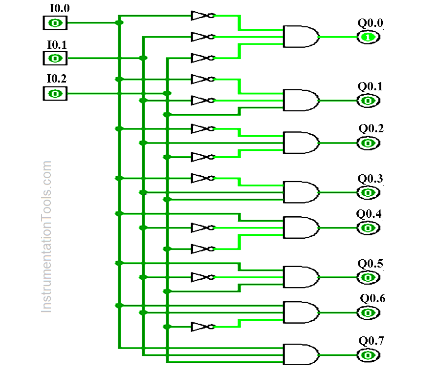
3 to 8 Line Decoder Circuit Diagram

Problem Solution

For this problem, we will use S7-1200 PLC and TIA portal software for programming.

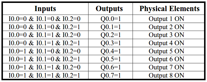
This decoder has three inputs and 8 outputs and these inputs determine which output will be ON.

Here three inputs were used (Input 1-I0.0, Input 2-I0.1, and Input 3-I0.2), and 8 outputs were used (Output 1 to 7, Q0.0 to Q0.7).

If all inputs are OFF, output 1 (Q0.0) will be ON and others are not.

List of inputs/outputs

List of inputs

  • Input 1:- I0.0
  • Input 2 :- I0.1
  • Input 3 :- I1.0

List of outputs

  • Output1 :- Q0.0
  • Output 2 :- Q0.1
  • Output 3 :- Q0.2
  • Output 4 :- Q0.3
  • Output 5 :- Q0.4
  • Output 6 :- Q0.5
  • Output 7 :- Q0.6
  • Output 8 :- Q0.7

PLC Program to implement 3 to 8 line decoder

PLC Program for Decoder Logic
Decoder PLC
3 to 8 line decoder
Decoder Ladder Logic
PLC Decoder Application
PLC Decoder Example
PLC Logic for Decoder
PLC Decoder Program

Program Description

For this application, we used S7-1200 PLC and TIA portal software for programming.

Network 1:

If all inputs are OFF (I0.0=0, I0.1=0 and I0.2=0), Output 1 (Q0.0) will be ON.

Network 2:

If input 1 (I0.0) and input 2 (I0.1) are OFF and input 3 (I0.2) is ON, Output 2 (Q0.1) will be ON.

Network 3:

If input 1 (I0.0) and input 3 (I0.2) are OFF and input 2 (I0.1) is ON, Output 3 (Q0.2) will be ON.

Network 4:

If input 2 (I0.1) and input 3 (I0.2) are ON and input 1 (I0.0) is OFF, Output 4 (Q0.3) will be ON.

Network 5:

If input 2 (I0.1) and input 3 (I0.2) are OFF and input 1 (I0.0) is ON, Output 5 (Q0.4) will be ON.

Network 6:

If input 1 (I0.0) and input 3 (I0.2) are ON and input 2 (I0.1) is OFF, Output 6 (Q0.5) will be ON.

Network 7:

If input 1 (I0.0) and input 2 (I0.1) are ON and input 3 (I0.2) is OFF, Output 7 (Q0.6) will be ON.

Network 8:

If input 1 (I0.0) and input 2 (I0.1) and input 3 (I0.2) are ON, Output 8 (Q0.7) will be ON.

Note :- Above application may be different from actual application. This example is only for explanation purpose only. We can implement this logic in other PLC also. This is the simple concept of 3 to 8 line decoder, we can use this concept in other examples also.

All parameters considered in example are for explanation purpose only, parameters may be different in actual applications. Also all interlocks are not considered in the application.

Result
3 to 8 Line Decoder

Author: Bhavesh

If you liked this article, then please subscribe to our YouTube Channel for PLC and SCADA video tutorials.

You can also follow us on Facebook and Twitter to receive daily updates.

Read Next:

  • PLC 3 Phase Asynchronous Motor Control
  • Energize & De-energize the Outputs using PLC
  • PLC Level Control of Parallel Tanks
  • GE PLC Ladder logic program download
  • Allen Bradley PLC Subroutines
Don't Miss Our Updates
Be the first to get exclusive content straight to your email.
We promise not to spam you. You can unsubscribe at any time.
Invalid email address
You've successfully subscribed !

Recommended Articles

FactoryTalk Studio and SQL Server for Data Logging
How Weigh Feeder Works ?
Automatic Sanitizer – Complex Ladder Logic PLC Examples
Ladder Logic Vs. Other Programming Languages – PLC Basics
Schneider Electric PLC Timer Problem: Vacuum Cleaner
Compare Two Offline PLC Projects
Share This Article
Facebook Whatsapp Whatsapp LinkedIn Copy Link
Share
Leave a Comment

Leave a Reply Cancel reply

Your email address will not be published. Required fields are marked *

Stay Connected

128.3kFollowersLike
69.1kFollowersFollow
208kSubscribersSubscribe
38kFollowersFollow

Categories

Recent Comments

  • William Snyder on Top Non-PLC Certification Courses for Automation Professionals
  • Kamli on Top Free PLC Software
  • Guifty Shimica on Top Non-PLC Certification Courses for Automation Professionals
  • Guifty Shimica on Top Non-PLC Certification Courses for Automation Professionals

Read More

[ruby_related total=6 layout=4 order=rand]

Related Articles

STAR DELTA Starter PLC Logic

STAR DELTA Programming using PLC Controller

Ladder Logic for Flow Meter Totalizer

Ladder Logic for Flow Meter Totalizer

Configuration of Siemens VFD Using TIA Portal

Configuration of Siemens VFD Using TIA Portal Start drive

Save to Memory Card

How to Save a PLC Project to a Micro Memory Card?

siemens plc db addressing

FB Block in Siemens PLC Programming

PLC based Automatic Packaging System

PLC based Automatic Packaging System

Yokogawa DCS

Yokogawa DCS and SIS System Architecture

PLC Memory Mapping

PLC Memory Mapping and I/O addressing

More Articles

Electronic Devices & Circuits Objective Questions

Electronic Devices & Circuits Quiz – Set 3

Communicating Delta PLC Software to Simulator

Multi-mode optical fiber

Multi-mode and Single-mode Optical Fibers

HMI screen for operator

Auto Tiffin Box Filling Station

Analyzers Questions and Answers

Analyzers Based on Gas Density Questions & Answers

Displacer Level Sensor Working Animation

Displacer Level Sensor Working Animation

Calculation of Hydrostatic Pressure

Calculation of Hydrostatic Pressure

PLC Programming Examples using Timer

Basic PLC Ladder Programming Example

Follow US
All rights reserved. Reproduction in whole or in part without written permission is prohibited.
Welcome Back!

Sign in to your account

Username or Email Address
Password

Lost your password?