Inst ToolsInst ToolsInst Tools
  • Courses
  • Automation
    • PLC
    • Control System
    • Safety System
    • Communication
    • Fire & Gas System
  • Instrumentation
    • Design
    • Pressure
    • Temperature
    • Flow
    • Level
    • Vibration
    • Analyzer
    • Control Valve
    • Switch
    • Calibration
    • Erection & Commissioning
  • Interview
    • Instrumentation
    • Electrical
    • Electronics
    • Practical
  • Q&A
    • Instrumentation
    • Control System
    • Electrical
    • Electronics
    • Analog Electronics
    • Digital Electronics
    • Power Electronics
    • Microprocessor
  • Request
Search
  • Books
  • Software
  • Projects
  • Process
  • Tools
  • Basics
  • Formula
  • Power Plant
  • Root Cause Analysis
  • Electrical Basics
  • Animation
  • Standards
  • 4-20 mA Course
  • Siemens PLC Course
Reading: T Flip Flop PLC Ladder Diagram
Share
Font ResizerAa
Inst ToolsInst Tools
Font ResizerAa
  • Courses
  • Design
  • PLC
  • Interview
  • Control System
Search
  • Courses
  • Automation
    • PLC
    • Control System
    • Safety System
    • Communication
    • Fire & Gas System
  • Instrumentation
    • Design
    • Pressure
    • Temperature
    • Flow
    • Level
    • Vibration
    • Analyzer
    • Control Valve
    • Switch
    • Calibration
    • Erection & Commissioning
  • Interview
    • Instrumentation
    • Electrical
    • Electronics
    • Practical
  • Q&A
    • Instrumentation
    • Control System
    • Electrical
    • Electronics
    • Analog Electronics
    • Digital Electronics
    • Power Electronics
    • Microprocessor
  • Request
Follow US
All rights reserved. Reproduction in whole or in part without written permission is prohibited.
Inst Tools > Blog > PLC Tutorials > T Flip Flop PLC Ladder Diagram

T Flip Flop PLC Ladder Diagram

This is a PLC Program to implement T flip flop. Learn the ladder diagrams with example-based programming.

Last updated: November 3, 2023 12:27 pm
Editorial Staff
PLC Tutorials
3 Comments
Share
3 Min Read
SHARE

This is a PLC Program to implement T flip flop. Learn the ladder diagrams with example-based programming.

Contents
T Flip Flop Logic using PLCProblem DiagramProblem SolutionList of inputs & outputsPLC Ladder DiagramProgram DescriptionResult

T Flip Flop Logic using PLC

Problem Description

Implement T flip flop in PLC using ladder diagram programming language.

Problem Diagram

T Flip Flop Logic using PLC Ladder Diagram

Problem Solution

We will use PLC S7-1200 for this application. We can implement this logic by using other PLC also.

T flip flop has two inputs, one is clock input and other one is T (toggle) input.

Ladder diagram of the T flip flop can be obtained by using T input in this flip flop.

This can be done by rising edge instruction. But many PLC’s do not have such type of instruction. So for that PLCs we can use this logic.

List of inputs & outputs

List of inputs

  • T (Toggle) :- I0.0

List of outputs

  • output (Light) :- Q0.0
  • One Shot (OS) logic output :- Q0.1

M memory

  • Relay coil :- M0.0

PLC Ladder Diagram

For easy understanding, here we assumed ” a Light ” is connected at output to check the flipflop logic status.

T Flip Flop PLC
T flip-flop PLC Ladder
PLC Logic T flip flop

Program Description

For this application, we used S7-1200 PLC and TIA portal software for programming.
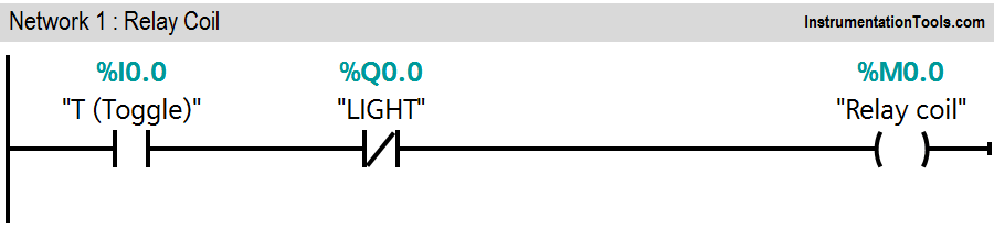
Network 1:

When T input (I0.0) is triggered, relay coil (M0.0) will go high immediately

Network 2:

During the second scan cycle, when Network 1 is scanned, status of Q0.1 is observed “1” .

Network 3:

When the network 3 is scanned, it receives input “1” from the image table which was set while scanning network 1. It triggers light output (Q0.0).

Even if T input is withdrawn, the light output (Q0.0) does not change. Even if the T input is withdrawn, the light output (Q0.0) does not change.

This logic can be implemented by using OSR instruction or rising edge of the PLC. Here we used only latching concept to hold the output.

Note:- This example is only for explanation purpose only. We can implement this logic in other PLC also. This is the simple concept of T flip flop, we can use this concept in other examples also.

All parameters considered in example are for explanation purpose only, parameters may be different in actual applications. Also all interlocks are not considered in the application.

Result

T flipflop PLC ladder

Author: Bhavesh

If you liked this article, then please subscribe to our YouTube Channel for PLC and SCADA video tutorials.

You can also follow us on Facebook and Twitter to receive daily updates.

Read Next:

  • PLC Multiple Outputs Configuration
  • Latching Function using PLC
  • NC Contact For Stop Buttons
  • DCS Interview Questions
  • RSLogix 5000 PLC Programming
Don't Miss Our Updates
Be the first to get exclusive content straight to your email.
We promise not to spam you. You can unsubscribe at any time.
Invalid email address
You've successfully subscribed !

Continue Reading

Applications of PLC Programming in Bottle Filling Process
PLC or DCS Control System Spares
PLC Programming for Tank Heating Control using Heater
Static and Temp Variables in PLC
How to Retrieve PLC Project From Memory Card?
Basic Arithmetic Programming in Mitsubishi PLC
Share This Article
Facebook Whatsapp Whatsapp LinkedIn Copy Link
Share
3 Comments
  • Archimedes says:
    September 9, 2018 at 8:14 pm

    thank you sir for all this helpfull articles! Just to inform you that i am still facing problems to download these tutorials to my PC even though i tried to use mozzilla as you told me earlier…Hope to find a solution to this problem. Thank you again!

    Reply
  • Jan Wieland says:
    March 12, 2021 at 7:26 pm

    In Network 1it should be %Q1.1 instead of %Q1.0.
    Otherwise it doesn´t work.

    Reply
  • Jan Wieland says:
    March 12, 2021 at 7:28 pm

    Oh, i meant %Q0.1 instead of %Q1.0, sorry

    Reply

Leave a Reply Cancel reply

Your email address will not be published. Required fields are marked *

Stay Connected

128.3kFollowersLike
69.1kFollowersFollow
210kSubscribersSubscribe
38kFollowersFollow

Categories

Explore More

1 to 8 Demultiplexer PLC ladder diagram
Difference Between PLC and SCADA
PLC Example with Switches
PLC System Site Acceptance Test (SAT)
Relay circuits
PLC Programming for Pumping and Draining System
Types of Interrupt OB in Siemens Tia Portal
Concept of Latching in PLC

Keep Learning

Edge Detection in PLC

Edge Detection in PLC Programming

Sharing data between two PLC systems

Distributed IO Sharing Between PLC Systems – Technical Insights

Communicating Delta PLC Software to Simulator

PLC Boxes Sorting Based on Height

PLC Programming: Sorting and Distribution of Boxes by Height

Concept of Interlocking in PLC

Concept of Interlocking in PLC

PLC Motor Control Circuit-3

Basics of PLC Programming

plc-analog-signals-wiring-techniques

PLC Analog Signals Wiring Techniques

How Engineers Effectively do Problem-solve and Troubleshoot

How Engineers Effectively do Problem-solve and Troubleshoot?

Learn More

Strain Gauge Pressure Sensor Principle

Strain Gauge Pressure Sensor Principle

Static and Temp Variables in PLC

Static and Temp Variables in PLC

Magnetostrictive Tank Gauging Probe

Magnetostrictive Tank Gauging (MTG)

Comparison of Proportional Integral Derivative Controllers (PID)

Comparison of Proportional Integral Derivative Controllers (PID)

PLC Program to Drain Same Products from Two Tanks

PLC Program to Drain Same Products from Two Tanks

Hazardous Area Classification Comparison

Comparison of IEC & NEC Area Classifications

Head Mount Temperature Transmitter

What is a Head Mount Temperature Transmitter? – Advantages

Mass Flow Calculations of flow measurement

Mass Flow Calculations

Menu

  • About
  • Privacy Policy
  • Copyright

Quick Links

  • Learn PLC
  • Helping Hand
  • Part Time Job

YouTube Subscribe

Follow US
All rights reserved. Reproduction in whole or in part without written permission is prohibited.
Welcome Back!

Sign in to your account

Username or Email Address
Password

Lost your password?