Inst ToolsInst ToolsInst Tools
  • Courses
  • Automation
    • PLC
    • Control System
    • Safety System
    • Communication
    • Fire & Gas System
  • Instrumentation
    • Design
    • Pressure
    • Temperature
    • Flow
    • Level
    • Vibration
    • Analyzer
    • Control Valve
    • Switch
    • Calibration
    • Erection & Commissioning
  • Interview
    • Instrumentation
    • Electrical
    • Electronics
    • Practical
  • Q&A
    • Instrumentation
    • Control System
    • Electrical
    • Electronics
    • Analog Electronics
    • Digital Electronics
    • Power Electronics
    • Microprocessor
  • Request
Search
  • Books
  • Software
  • Projects
  • Process
  • Tools
  • Basics
  • Formula
  • Power Plant
  • Root Cause Analysis
  • Electrical Basics
  • Animation
  • Standards
  • 4-20 mA Course
  • Siemens PLC Course
Reading: DC Circuit Analysis Node Equations
Share
Font ResizerAa
Inst ToolsInst Tools
Font ResizerAa
  • Courses
  • Design
  • PLC
  • Interview
  • Control System
Search
  • Courses
  • Automation
    • PLC
    • Control System
    • Safety System
    • Communication
    • Fire & Gas System
  • Instrumentation
    • Design
    • Pressure
    • Temperature
    • Flow
    • Level
    • Vibration
    • Analyzer
    • Control Valve
    • Switch
    • Calibration
    • Erection & Commissioning
  • Interview
    • Instrumentation
    • Electrical
    • Electronics
    • Practical
  • Q&A
    • Instrumentation
    • Control System
    • Electrical
    • Electronics
    • Analog Electronics
    • Digital Electronics
    • Power Electronics
    • Microprocessor
  • Request
Follow US
All rights reserved. Reproduction in whole or in part without written permission is prohibited.
Inst Tools > Blog > Electrical Theory > DC Circuit Analysis Node Equations

DC Circuit Analysis Node Equations

Last updated: July 25, 2018 4:14 pm
Editorial Staff
Electrical Theory
No Comments
Share
4 Min Read
SHARE

All of the rules governing DC circuits that have been discussed so far can now be applied to analyze complex DC circuits. To apply these rules effectively, loop equations, node equations, and equivalent resistances must be used.

Node Equations

Kirchhoff’s current law, as previously stated, says that at any junction point in a circuit the current arriving is equal to the current leaving. Let us consider five currents entering and leaving a junction shown as P (Figure 43). This junction is also considered a node.

Assume that all currents entering the node are positive, and all currents that leave the node are negative. Therefore, I1 ,I3 , and I4 are positive, and I2 and I5 are negative. Kirchhoff’s Law also states that the sum of all the currents meeting at the node is zero. For Figure 43, Below Equation represents this law mathematically.

I1 + I2 + I3 + I4 + I5 = 0

DC Circuit Node Equations

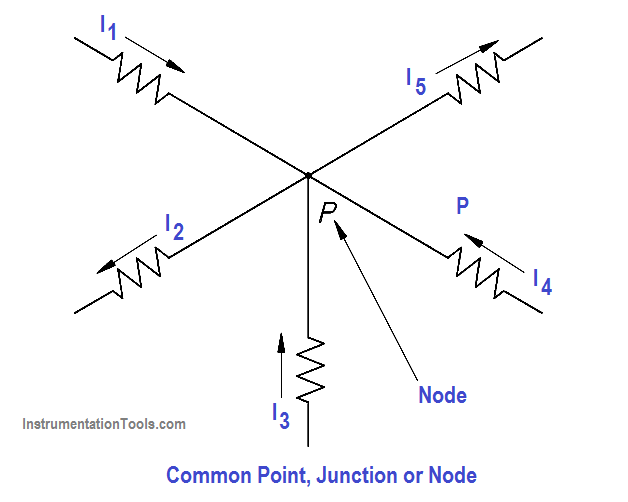
Figure 43 Node Point

By solving node equations, we can calculate the unknown node voltages. To each node in a circuit we will assign a letter or number. In Figure 44, A, B, C, and N are nodes, and N and C are principal nodes. Principal nodes are those nodes with three or more connections. Node C will be our selected reference node.

VAC is the voltage between Nodes A and C; VBC is the voltage between Nodes B and C; and VNC is the voltage between Nodes N and C. We have already determined that all node voltages have a reference node; therefore, we can substitute VA for VAC , VB for VBC , VN for VNC.

Circuit for Node Analysis

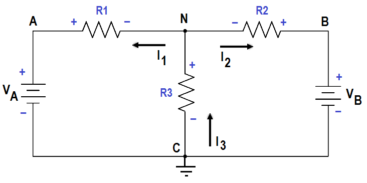
Figure 44 Circuit for Node Analysis

Assume that loop currentsI1 and I2 leave Node N, and that I3 enters Node N (Figure 44).

From Kirchhoff’s current law:

∑ I = 0

I1 + I2 + I3 = 0

I3 = I1 + I2

Using Ohm’s Law and solving for the current through each resistor we obtain the following.

Electric Circuit Node Equations

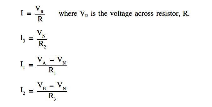
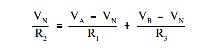
Substitute these equations for I1 ,I2 , and I3 into Kirchhoff’s current equation yields the following.

Electric Circuit Node Equations - 1

The circuit shown in Figure 45 can be solved for voltages and currents by using the node-voltage analysis.

Node - Voltage Analysis

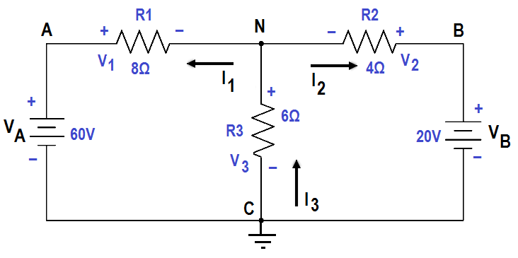
Figure 45 Node – Voltage Analysis

First, assume direction of current flow shown. Mark nodes A, B, C, and N, and mark the polarity across each resistor.

Second, using Kirchhoff’s current law at Node N, solve for VN.

Kirchhoff’s current law at Node

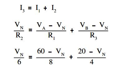
Clear the fraction so that we have a common denominator:

4VN = 3 (60 – VN) + 6 (20 – VN)

4VN= 180 – 3VN + 120 – 6VN

13VN = 300

VN = 23.077

Third, find all voltage drops and currents.

V1 = VA – VN = 60 – 23.077 = 36.923 Volts

V2 = VN = 23.077 Volts

V3 = VB – VN = 20 – 23.077 = -3.077 Volts

The negative value for V3 shows that the current flow through R3 is opposite that which was assumed and that the polarity across R3 is reversed.

I1 = V1/R1 = 36.923 / 8 = 4.65 amp

I2 = V2/R2 = 23.077 / 6 = 3.846 amp

I3 = V3/R3 = -3.077 / 4 = – 0.769 amp

The negative value for I3 shows that the current flow through R3 is opposite that which was assumed.

Don't Miss Our Updates
Be the first to get exclusive content straight to your email.
We promise not to spam you. You can unsubscribe at any time.
Invalid email address
You've successfully subscribed !

Continue Reading

Calculate Power in Series RCL Circuit
Power Factor
Low Voltage Protection (LVP) and Low Voltage Release (LVR)
AC Generation
Three Phase AC Generators
Methods of Producing Voltage (Electricity)
Share This Article
Facebook Whatsapp Whatsapp LinkedIn Copy Link
Share
Leave a Comment

Leave a Reply Cancel reply

Your email address will not be published. Required fields are marked *

Stay Connected

128.3kFollowersLike
69.1kFollowersFollow
210kSubscribersSubscribe
38kFollowersFollow

Categories

Explore More

DC Generator
3-Wire, Three-Phase Delta Wiring System
Transformer Current Ratio
Capacitance and Capacitive Reactance
AC Generation Analysis : Effective Values, Phase Angle and Frequency
Generator Action in a Motor
Resistance in Parallel Circuits
Parallel AC Generators

Keep Learning

Single Phase Motor Manual Controller

Motor Controllers

Voltage Drop in a Series Circuit

Series Resistance

Power Factor Meter Principle

Power Factor Meter Principle

Thermocouples

Thermocouples

Compounded DC Generator

Compound Generators

Transformer Coil Polarity

Transformer Coil Polarity

Gang Switch Principle

Reading Electrical Schematics

Shorted Parallel Circuit

Parallel Short Circuit Faults

Learn More

Electrical Feeder Automation in Smart Grid

Electrical Feeder Automation in Smart Grid

PLC FBD Example for Tank Liquid Heating Control by Steam Flow

PLC FBD Example for Tank Liquid Heating Control by Steam Flow

Improved Sprocket Segment Bolting to body

A Plant Bucket Elevators chains too short chain lives problem eliminated

How are Data Centers Cooled

How are Data Centers Cooled?

MOSFET VI Characteristics

Power MOSFET

Level Sensors MCQ

Level Sensors MCQ – Industrial Instrumentation

Electricity Generated From Wind Energy

How is Electricity Generated From Wind Energy?

valve packing assembly

What is Valve Packing ?

Menu

  • About
  • Privacy Policy
  • Copyright

Quick Links

  • Learn PLC
  • Helping Hand
  • Part Time Job

YouTube Subscribe

Follow US
All rights reserved. Reproduction in whole or in part without written permission is prohibited.
Welcome Back!

Sign in to your account

Username or Email Address
Password

Lost your password?