Balanced loads, in a 3φ system, have identical impedance in each secondary winding (Figure 12). The impedance of each winding in a delta load is shown as Z∆ (Figure 12a), and the impedence in a wye load is shown as Zy (Figure 12b). For either the delta or wye connection, the lines A, B, and C supply a 3φ system of voltages.
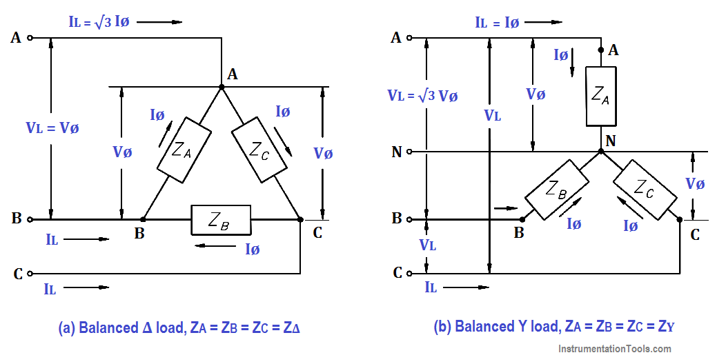
Figure 12 : 3φ Balanced Loads
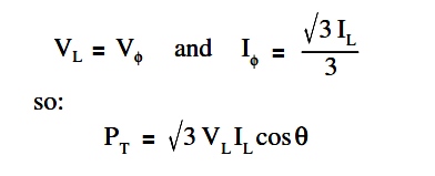
In a balanced delta load, the line voltage (VL) is equal to the phase voltage (Vø), and the line current (IL) is equal to the square root of three times the phase current (√3Iø).
The below Equation is a mathematical representation of VL in a balanced delta load.
VL = Vø
The below Equation is a mathematical representation of IL in a balanced delta load.
IL =√3Iø
In a balanced wye load, the line voltage (VL) is equal to the square root of three times phase voltage (√3Vø), and line current (IL) is equal to the phase current (Iø).
The below Equation is a mathematical representation of VL in a balanced wye load.
VL = √3Vø
The below Equation is a mathematical representation of IL in a balanced wye load.
IL = Iø
Because the impedance of each phase of a balanced delta or wye load has equal current, phase power is one third of the total power.
The below Equation is the mathematical representation for phase power (Pø) in a balanced delta or wye load.
Pø = Vø Iø cosθ
Total power (PT) is equal to three times the single-phase power.
The below Equation is the mathematical representation for total power in a balanced delta or wye load.
PT = 3 Vø Iø cosθ
In a delta-connected load,
In a wye-connected load,
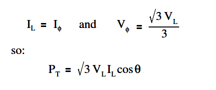
As you can see, the total power formulas for delta- and wye-connected loads are identical.
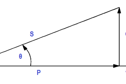
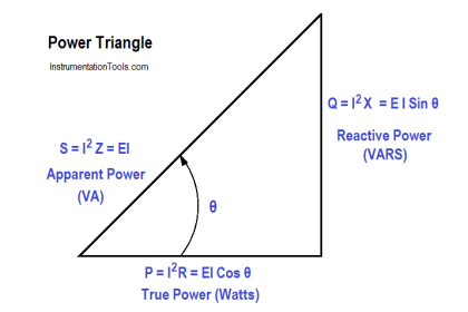
Total apparent power (ST) in volt-amperes and total reactive power (QT) in volt-amperes-reactive are related to total real power (PT) in watts (Figure 13).
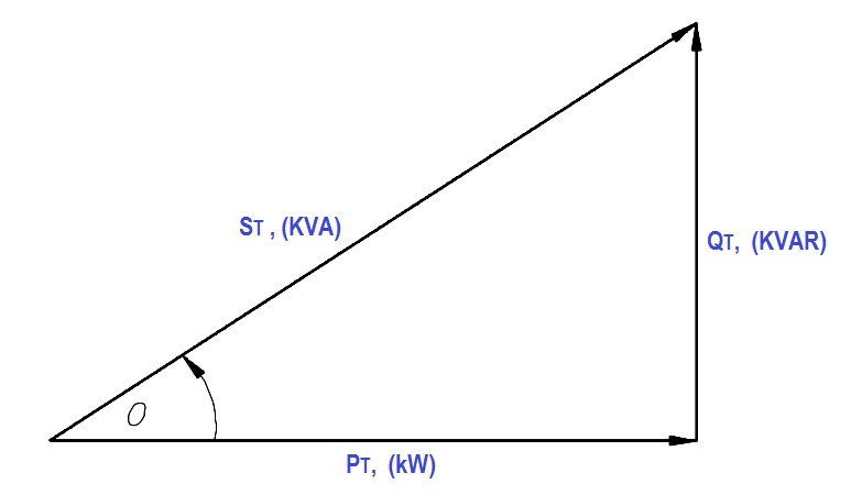
Figure 13 : 3φ Power Triangle
A balanced three-phase load has the real, apparent, and reactive powers given by:
Example 1:
Each phase of a delta- connected 3φ AC generator supplies a full load current of 200 A at 440 volts with a 0.6 lagging power factor, as shown in Figure 14.
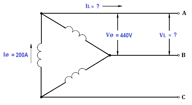
Figure 14 : Three-Phase Delta Generator
Find:
- VL
- IL
- PT
- QT
- ST
Solution :
1. Calculate VL
VL = Vø
VL = 440V
2. Calculate IL
IL =√3Iø
IL = 1.73 x 200
IL = 346 amps
3. Calculate PT
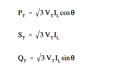
PT = √3 VL IL cosθ
PT = 1.73 x 440 x 346 x 0.6
PT = 158.2 kW
4. Calculate QT
QT = √3 VL IL sinθ
QT = 1.73 x 440 x 346 x 0.8
QT = 210.7 KVR
5. Calculate ST
ST = √3 VL IL
ST = 263.4 KVA
Example 2:
Each phase of a wye- connected 3φ AC generator supplies a 100 A current at a phase voltage of 240V and a power factor of 0.9 lagging, as shown in Figure 15.
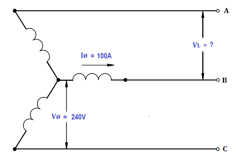
Figure 15 : Three-Phase Wye Generator
Find:
- VL
- PT
- QT
- ST
Solution :
1. Calculate VL
VL = √3Vø
VL = 1.73 x 240
VL = 415.2 volts
2. Calculate PT
PT = √3 VL IL cosθ
PT = 1.73 x 415.2 x 100 x 0.9
PT = 64.6 kW
3. Calculate QT
QT = √3 VL IL sinθ
QT = 1.73 x 415.2 x 100 x 0.436
QT = 31.3 KVAR
4. Calculate ST
ST = √3 VL IL
ST = 1.73 x 415.2 x 100
ST = 71.8 KVA


The explanation was so simple to be understood