Inst ToolsInst ToolsInst Tools
  • Courses
  • Automation
    • PLC
    • Control System
    • Safety System
    • Communication
    • Fire & Gas System
  • Instrumentation
    • Design
    • Pressure
    • Temperature
    • Flow
    • Level
    • Vibration
    • Analyzer
    • Control Valve
    • Switch
    • Calibration
    • Erection & Commissioning
  • Interview
    • Instrumentation
    • Electrical
    • Electronics
    • Practical
  • Q&A
    • Instrumentation
    • Control System
    • Electrical
    • Electronics
    • Analog Electronics
    • Digital Electronics
    • Power Electronics
    • Microprocessor
Search
  • Books
  • Software
  • Projects
  • Process
  • Tools
  • Basics
  • Formula
  • Power Plant
  • Root Cause Analysis
  • Electrical Basics
  • Animation
  • Standards
  • 4-20 mA Course
  • Siemens PLC Course
Reading: Open Tank DP Level Transmitter Calculations
Share
Notification Show More
Font ResizerAa
Inst ToolsInst Tools
Font ResizerAa
  • Courses
  • Design
  • PLC
  • Interview
  • Control System
Search
  • Courses
  • Automation
    • PLC
    • Control System
    • Safety System
    • Communication
    • Fire & Gas System
  • Instrumentation
    • Design
    • Pressure
    • Temperature
    • Flow
    • Level
    • Vibration
    • Analyzer
    • Control Valve
    • Switch
    • Calibration
    • Erection & Commissioning
  • Interview
    • Instrumentation
    • Electrical
    • Electronics
    • Practical
  • Q&A
    • Instrumentation
    • Control System
    • Electrical
    • Electronics
    • Analog Electronics
    • Digital Electronics
    • Power Electronics
    • Microprocessor
Follow US
All rights reserved. Reproduction in whole or in part without written permission is prohibited.
Inst Tools > Blog > Formulas > Open Tank DP Level Transmitter Calculations

Open Tank DP Level Transmitter Calculations

Open Tank DP Level Transmitter Calculations for DP Transmitter installed at the exact at HP tapping point and below HP tapping point of the tank.

Last updated: September 21, 2020 4:57 pm
Editorial Staff
Formulas Guest Articles Level Measurement
6 Comments
Share
3 Min Read
SHARE

In any process industry, level measurement is very important for safety and process purpose.

Contents
DP Transmitter Level Measurement for Open TankDP Transmitter installed at the exact HP tapping pointDP Transmitter Installed Below Tapping Point for Open Tank

Level can be measured by two methods.

  1. Direct method
  2. Indirect method

Here we discuss about indirect method and which is using DP transmitter for level measurement.

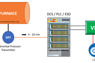
A Differential pressure transmitter is a common and well understood technology for liquid level measurement. If the tank is closed or pressurized, a DP measurement must be made to compensate for the vessel pressure.

DP Transmitter Level Measurement for Open Tank

Suppose there is a open tank in which a DP transmitter installed for the measurement of level then HP leg of the DP transmitter is connected with bottom of tank and LP leg is open in atmosphere. Assume process fluid specific gravity in the tank is 1.0

Definition of specific gravity: Specific gravity is a measure of density relative to the density of a reference substance. Reference substance is taken water.

For DP Transmitter Configuration, we have to find out Zero Level & Span Level. Accordingly we have to configure Lower Range Value (LRV) and Upper Range Value (URV) using HART communicator.

DP Transmitter installed at the exact HP tapping point

Open Tank DP Level Measurement

At Zero level = 0 mmwc
At Span level = H x Specific gravity

= 500 x 1.0

 = 500 mmwc

Then Range = 500 – 0 = 500 mmwc

So, we have to set Lower Range Value (LRV) = 0 mmwc and Upper Range Value (URV) = 500 mmwc in the DP Transmitter using HART communicator.

DP Transmitter Installed Below Tapping Point for Open Tank

If transmitter is installed below the tank then it’s called zero suppression then calculation is below:

DP Transmitter Installed Below Tapping Point for Open Tank

When zero suppression is used then H1 height always filled with process fluid.

At zero level (LRV) = H1 x specific gravity

= 100 x 1.0

= 100 mmwc

At 100% level (URV) = (H1 + H2) x specific gravity

= (100 + 500) x 1.0

= 600 mmwc

Range = URV – LRV = 600 – 100 = 500 mmwc

So, we have to set Lower Range Value (LRV) = 100 mmwc and Upper Range Value (URV) = 600 mmwc in the DP Transmitter using HART communicator.

Author: Ashish Agrawal

Read Next:

  • Transmitter Turndown Ratio
  • DP Transmitter Zero Suppression
  • Cat & Mouse type Level Indicator
  • Tilt Level Switch Working
  • Point Level Detection
Don't Miss Our Updates
Be the first to get exclusive content straight to your email.
We promise not to spam you. You can unsubscribe at any time.
Invalid email address
You've successfully subscribed !

Continue Reading

How Tilt Level Switch Works ?
How to Convert Cable Size from AWG to Inches
Nuclear Level Detectors Cascade or Master/Slave concept
Surface Detector Level Gauges (Plumb-bob)
Blast Furnace Panel Modification to Reduce Down Time by 60 to 70%
Magnetic Float Level Transmitter Working Principle
Share This Article
Facebook Whatsapp Whatsapp LinkedIn Copy Link
Share
6 Comments
  • Kalyani bahubali says:
    March 10, 2018 at 4:11 am

    Very good knowledge…..

    Reply
  • Kevin says:
    August 3, 2021 at 3:17 pm

    Wonderful piece, I enjoyed it all the way.

    Reply
  • Alam Shabaz says:
    November 6, 2022 at 7:35 pm

    If LRV = 100 And URV = 600 Then What is This
    Range 500 mmwc

    Reply
    • TANK says:
      August 1, 2024 at 8:15 pm

      SPAN RANGE 500 MMWC

      Reply
  • Joe says:
    November 15, 2022 at 2:38 am

    Great Info I appreciate

    Reply
  • Mohan Krishna says:
    February 29, 2024 at 1:54 pm

    Dear sir kindly update for calibration procedure for Gas sensors

    Reply

Leave a Reply Cancel reply

Your email address will not be published. Required fields are marked *

Stay Connected

128.3kFollowersLike
69.1kFollowersFollow
210kSubscribersSubscribe
38kFollowersFollow

Categories

Explore More

Types of Industrial Level Sensors
Guided Wave Radar Questions and Answers
4-20mA Junction Box versus Fieldbus (FF) Junction Box
Float level switch Principle
Wrong Installation of Horn Type Radar Level Transmitter on Sloping Tank
Inhouse Moisture separator for Pneumatic Systems
PLC Raw Count Calculation for Pressure Transmitter
Closed Tank Remote Seal Capillary type DP Transmitter

Keep Learning

Gas flow rate Formulas

Gas Flow Formulas

Field Transmitter Range Calculation

Transmitter Turndown Ratio, Set Span and Zero Span

Vibrating Fork Level Switch Working Animation

Vibrating Fork Level Switch Working Animation

Differential Pressure Transmitter Wet Leg Compensation

Differential Pressure Transmitters Compensated Leg Systems

Closed Tank Non-Zero-Based Direct Mount Application

Open and Closed Tank Level Calculations

Device Connected to MODEM

Internal Powered Modems

Rotary Level Switch Working Principle Animation

Rotary Level Switch Working principle Animation

Field Instrument 4-20mA Calculation

How to do 4-20mA Conversions Easily

Learn More

Boiler Light-Up Sequence - Power Plant Operation

Boiler Light-Up Sequence – Power Plant Operation

Power Electronics Objective Questions

Quiz on Type E Choppers

UL 489 Circuit Breaker

Difference Between UL489 and UL1077

Load Cell Assembly

Urea Bagging Plant – Process Flow

TON Timer in RSlogix

Why is RTO used in the Place of TON Timer?

Types of Pressure Measuring Scales

Types of Pressure Measuring Scales

Instrument Loop Diagram

How-to Create Instrument Loop Diagram (ILD)?

PLC Program

Example PLC Program

Menu

  • About
  • Privacy Policy
  • Copyright

Quick Links

  • Learn PLC
  • Helping Hand
  • Part Time Job

YouTube Subscribe

Follow US
All rights reserved. Reproduction in whole or in part without written permission is prohibited.
Welcome Back!

Sign in to your account

Username or Email Address
Password

Lost your password?