Inst ToolsInst ToolsInst Tools
  • Courses
  • Automation
    • PLC
    • Control System
    • Safety System
    • Communication
    • Fire & Gas System
  • Instrumentation
    • Design
    • Pressure
    • Temperature
    • Flow
    • Level
    • Vibration
    • Analyzer
    • Control Valve
    • Switch
    • Calibration
    • Erection & Commissioning
  • Interview
    • Instrumentation
    • Electrical
    • Electronics
    • Practical
  • Q&A
    • Instrumentation
    • Control System
    • Electrical
    • Electronics
    • Analog Electronics
    • Digital Electronics
    • Power Electronics
    • Microprocessor
  • Request
Search
  • Books
  • Software
  • Projects
  • Process
  • Tools
  • Basics
  • Formula
  • Power Plant
  • Root Cause Analysis
  • Electrical Basics
  • Animation
  • Standards
  • 4-20 mA Course
  • Siemens PLC Course
Reading: Gas chromatograph Working Animation
Share
Font ResizerAa
Inst ToolsInst Tools
Font ResizerAa
  • Courses
  • Design
  • PLC
  • Interview
  • Control System
Search
  • Courses
  • Automation
    • PLC
    • Control System
    • Safety System
    • Communication
    • Fire & Gas System
  • Instrumentation
    • Design
    • Pressure
    • Temperature
    • Flow
    • Level
    • Vibration
    • Analyzer
    • Control Valve
    • Switch
    • Calibration
    • Erection & Commissioning
  • Interview
    • Instrumentation
    • Electrical
    • Electronics
    • Practical
  • Q&A
    • Instrumentation
    • Control System
    • Electrical
    • Electronics
    • Analog Electronics
    • Digital Electronics
    • Power Electronics
    • Microprocessor
  • Request
Follow US
All rights reserved. Reproduction in whole or in part without written permission is prohibited.
Inst Tools > Blog > Analyzers > Gas chromatograph Working Animation

Gas chromatograph Working Animation

Last updated: September 9, 2017 3:33 am
Editorial Staff
Analyzers Animation How It Works
1 Comment
Share
1 Min Read
SHARE

Gas chromatograph Working Animation shows the operation philosophy of GC functionality. 

Gas chromatograph Working Animation
Pic Credits : Emerson

GC Working Principle Briefly :

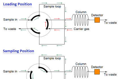
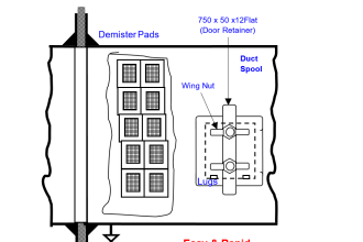
  • The sample gas will be taken from the Process pipe line through GC Sampling system.
  • A carrier gas (generally Helium) will be used to carry out the collected sample gas through the GC column.
  • The GC Column will be maintained at a standard temperature (85 deg c, changes from vendor to vendor) with the heater.
  • The sample gas will be heated for a certain time in the column. So that all components in the sample gas will be separated in the column.
  • The separated components will travel from column to the detector individually.
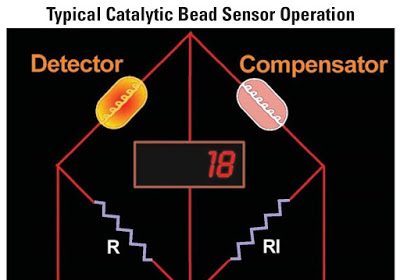
  • The detector will detect the respective component voltage.
  • Thus finally we measure all individual components in the sample gas.
  • We plot all measured components in a graph called chromatogram.

Also Read: Complete Working Principle of Gas Chromatograph

Don't Miss Our Updates
Be the first to get exclusive content straight to your email.
We promise not to spam you. You can unsubscribe at any time.
Invalid email address
You've successfully subscribed !

Continue Reading

Selection Criteria of pH Analyzers
Gas Filter Correlation (GFC) Spectroscopy
Basics of Globe Valves
Understanding the Scan Cycle of SIEMENS PLC
What is the Application of Electrical Conductivity Meter?
Working Principle of Flow Switch with Animation
Share This Article
Facebook Whatsapp Whatsapp LinkedIn Copy Link
Share
1 Comment
  • Babu says:
    July 14, 2015 at 1:48 am

    I am just Loved thus animation. And easily I am understand the GC Working also. Thanks for sharing. Keep it up.

    Reply

Leave a Reply Cancel reply

Your email address will not be published. Required fields are marked *

Stay Connected

128.3kFollowersLike
69.1kFollowersFollow
210kSubscribersSubscribe
38kFollowersFollow

Categories

Explore More

4-20mA Junction Box versus Fieldbus (FF) Junction Box
Motor Classic Control Circuits using Single Push button
Magnetic Float Level Switch Working Animation
Thermal Conductivity Detector (TCD) Principle
Oxidation-Reduction Potential (ORP) Sensor Calibration Procedure
Sling Psychrometer Principle
Humidity Sensing Absorption Hydrometer Principle
Chlorine dioxide Analyzer Principle

Keep Learning

Two Wire Sensors Animation

Two Wire Sensor Working Principle and Animation

CEMS Classification

CEMS Principle, Types, Advantages, and Disadvantages

toroidal conductivity probe principle

Conductivity Analyzer Common Problems and Troubleshooting Tips

AND Gate Logic Animation

Digital Building Blocks – GATES

Dissolved Oxygen Analyzers Interview Questions

Dissolved Oxygen Analyzer Interview Questions & Answers

H & B Gas Analyzer Principle and Calibration Procedure

Conductivity Analyzer Principle

Conductivity Analyzers Interview Questions & Answers

Control Valve Working Animation

Control Valve Working Animation

Learn More

PLC Project Examples for EcoStruxure Machine Expert

PLC Project Examples for EcoStruxure Machine Expert

Power MOSFET Symbols

Power MOSFET – Symbol, Types, Working, Characteristics, Advantages

statuses of all lamps and relay coils in the circuit

Analyze the Relay Circuit and Find the Status ?

Transformers Questions & Answers Part-2

Transformers Questions & Answers Part-2

In-Situ Zirconia Oxygen Analyzer

Oxygen (O2) Measurement in Flue Gas

Turbine Flow meter calibration

Turbine Flow Meter Calibration

Basic Requirements of Sizing the Control Valves

Basic Requirements of Control Valves Sizing

Control Valves Chemical attack Problems

Control Valves Chemical attack Problems

Menu

  • About
  • Privacy Policy
  • Copyright

Quick Links

  • Learn PLC
  • Helping Hand
  • Part Time Job

YouTube Subscribe

Follow US
All rights reserved. Reproduction in whole or in part without written permission is prohibited.
Welcome Back!

Sign in to your account

Username or Email Address
Password

Lost your password?