CEMS stands for Continuous Emission Monitoring System. It is a analyzer used to measure different gas concentrations in the industries.
Need for CEMS
Industries like Power plants, Cement, Fertilizers, Iron & Steel, Chlor-alkali, Pharma, Refineries, Pesticides, Sugar, Pulp & Paper, Textile, and other categories of industries release large quantum of pollutants through air emissions and effluent discharge.
Various CEMS
CEMS provides accurate and continuous measurement information on the particulate matter/ gaseous emission from stacks. Depending upon the specific industry, stack emissions are monitored continuously.
There are systems available for monitoring parameters like
Particulate Matter (PM),
HCl – Hydrochloric acid
HF – as Total fluoride
NH3 – as Ammonia
SO2 – Sulphur di-oxide
CO – Carbon monoxide
O2 – Oxygen
CO2 – Carbon dioxide
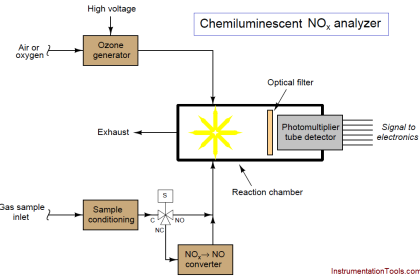
NOx – Oxides of Nitrogen as NO2. etc.
Objectives of CEMS
- Avoiding environmental contamination
- Compliance with legislation
- It gives insight into the operational efficiency of a company.
The significant advantages of CEMS over traditional laboratory-based and portable field methods are:
- CEMS provides continuous measurement of data for long periods of time.
- Sample collection, transportation, conditioning, calibration, and analysis procedures including QC are totally automated.
- Any unforeseen disturbance within the Production Process/ Pollution Control system, the on-line analyzers provide timely information for taking immediate corrective/preventive steps.
CEMS Classification
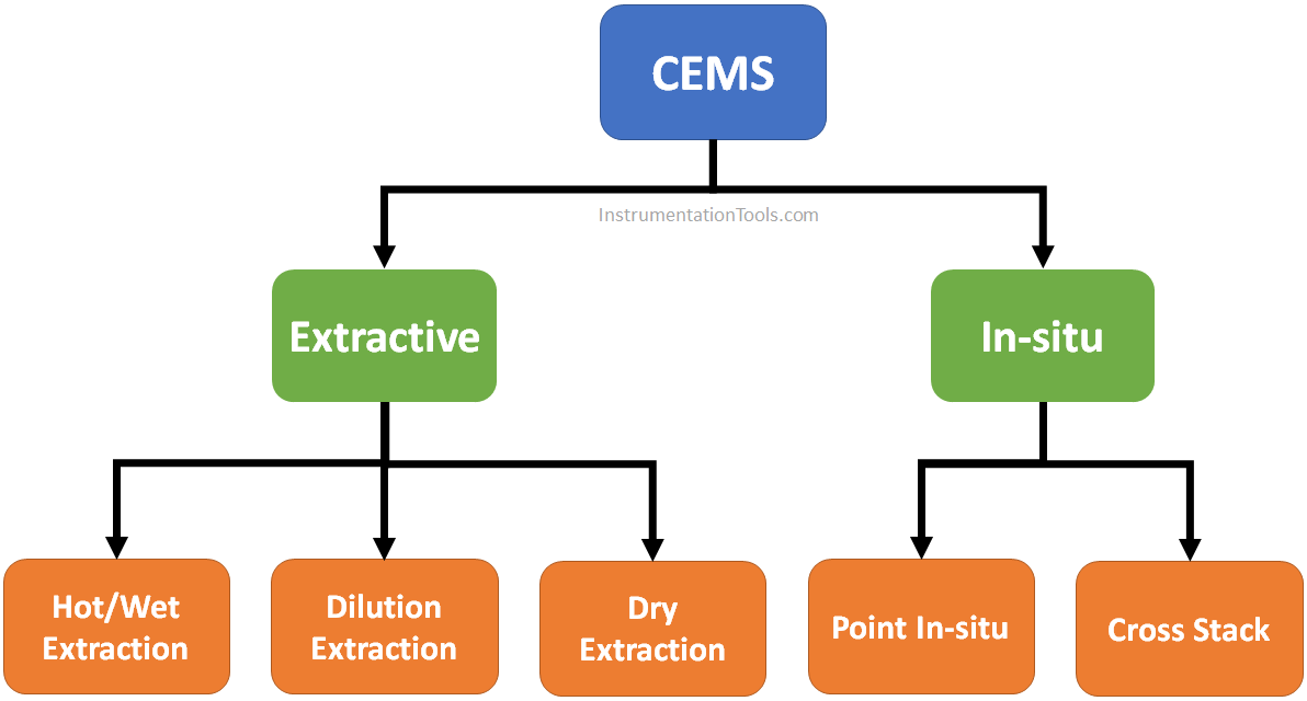
- In Situ system: In-situ is defined as in the situation.
- Extractive system.
Again, In-situ type analyzers may be of two types:
- Point in-situ type.
- Cross stack type.
Point in-situ
Systems perform sample collection at a single point in the stack and measurements accordingly, as do extractive system probes. In the in-situ systems, the sensing optics are contained in a cylindrical tube fitted with holes or filters to allow flow-through of stack gases into it.
The sampling path will be relatively short compared to the stack or duct diameter, so the sampling location must be carefully chosen to ensure that the sample is representative of the flue gas.
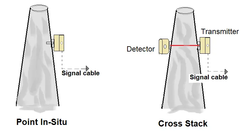
Cross Stack
In this method, the system monitors across the length of the diameter of the stack. An optical beam at a certain wavelength is sent across the stack diameter. Signal attenuation is measured on the other end, attenuation is signal is proportional to the concentration of the emissions.
Advantages
- As the sensor is very close to the process, the response time is faster.
- Simple installation, special measures for sample gas extraction is not required.
Disadvantages
- Sensors may be getting exposed to potentially corrosive gases.
- Installation may get subjected to vibration and high temperature.
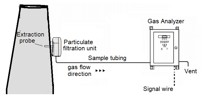
Extractive system
In this type, a sample of flue gases are continuously extracted from a point and pumped up to the analyzer using a sampling line.
Impurities and water may be removed from the gas, and it may be cooled and dried, but in all other respects, the sample is not altered by the sampling process. This set up is very convenient and protects the device from harmful exposure to the plant environment.
Hot/Wet Extraction
Measures the hot wet gases without removing the moisture. The sample transport line is heated to a predetermined temperature to keep the moisture not to condense.
Dilution Extraction
An addition of a known quantity of clean dry air immediately to the extracted sample after it is removed from the stack.
Dry Extraction
Stack gas is transported to the analyzer, where it passed through the chiller to remove moisture.
Advantage
- Easier maintenance and calibration.
Disadvantages
- Extraction systems become expensive than in Situ If only one gas measurement is required.
- Sample tubing and associated measures as the sample tube is layed between the extraction point and analyzer.
- Moisture in the sampling system can be a significant problem.
Types
There are several measurement procedures, we discuss here only two Oxygen concentration measurement methods.
- Zirconium Oxide (ZrO2) Analyzer.
- Paramagnetic Automatic Null-Balance Analyzers.
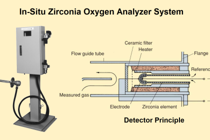
Zirconium Oxide (ZrO2) Analyzer for Oxygen measurement
This Analyzers uses ZrO2 for the measurement of oxygen concentration.
In this method, a ceramic material, Zirconium Oxide (ZrO2) coated with a thin layer of platinum metal, acts as an electrolyte to allow the transfer of oxygen from one side of the cell to the other. In the cell, the oxygen concentration within the reference side is maintained at 21%.
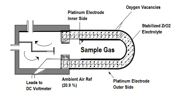
When the sample side of the cell is exposed to flue gases, the oxygen concentration in the sample side will be less than that in the reference side. When ZrO2 is heated to around 600°C, oxygen ions can migrate through the material, releasing electrons in the process.
This results in the generation of an electromotive force (emf), which is proportional to the difference in oxygen concentration between the two sides of the cell. If the reference oxygen concentration is known, the sample concentration can be computed.
The main characteristics of these analyzers are:
- Very accurate and reliable measurement of O2;
- A fast response time (for in-situ measurement) makes it perfect for process control applications;
- It is a well-understood technology with examples at most boiler units (for combustion control);
- It has a low budget cost and low maintenance/
Paramagnetic Automatic Null-Balance Analyzers
The oxygen molecules in a flowing gas sample will lean in a magnetic field due to the partial pressure gradient.
The flue gas sample intake chamber consists of two nitrogen-filled glass spheres that are mounted on a suspension. As the flue gas passes through the arrangement, only oxygen molecules get attracted to the magnetic field.
With the generated magnetic force in the chamber causes the nitrogen sphere arrangement a displacement movement.

The displacement is detected by a mirror and photocell assembly, which measures its angular position. The strength of the torque acting on the suspension is proportional to the oxygen concentration in the surrounded flue gases.
The torque on the suspension is balanced by restoring torque due to the compensation current in the coil. This compensation current is proportional to the O2 concentration of the sample gas.
- The paramagnetic cell measurement principle can achieve high sensitivity and accuracy.
- Oxygen at any level in the range of 0-100% in the gas mixture can be analyzed.
- This type of analyzer has become a standard for flue gas analysis and is also type-approved for continuous emission monitoring.
Read Next:
- pH Analyzer Calibration
- Troubleshoot Oxygen Sensor
- Ammonia Analyzer Principle
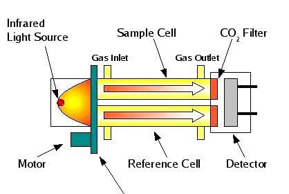
- Non-Dispersive Analyzers
- Turbidity Analyzer Principle


what is the manual sampling method /procedure for measuring particulate matter in thermal power plant stack? And what is the best procedure to calibrate the opacity dust monitors in stack?
can we use central system for many stacks and connecting to same device to monitoring the emission and what the disadvantage of the central monitoring system?