Inst ToolsInst ToolsInst Tools
  • Courses
  • Videos
  • Q & A
    • Interview
      • Instrumentation
      • Electronics
      • Electrical
      • Practical Questions
    • MCQ
      • Instrumentation MCQ
      • Electrical MCQ
      • Electronics MCQ
      • Control Systems MCQ
      • Analog Electronics MCQ
      • Digital Electronics MCQ
      • Power Electronics MCQ
      • Microprocessor MCQ
      • Multiple Choice Questions
  • EE
    • Electronics
      • Electronics Q & A
      • Electronic Basics
      • Electronic Devices & Circuits
      • Electronics Animation
      • Digital Electronics
    • Electrical
      • Electrical Basics
      • Electrical Q & A
      • Power Electronics
      • Electrical Machines
      • Electrical Animation
      • Power Systems
      • Switchgear & Protection
      • Transmission & Distribution
  • Measure
    • Control Valves
    • Calibration
    • Temperature
    • Pressure
    • Flow
    • Level
    • Analyzers
    • Switches
    • Vibration
    • Solenoid Valve
  • Control
    • PLC Tutorials
    • Control Systems
    • Safety Instrumented System (SIS)
    • Communication
    • Fire & Gas System
  • More
    • Design
    • Tools
    • Animation
    • Basics
    • Formulas
    • Standards
    • TextBooks
    • Common
    • Software
    • Excel Tools
    • Erection & Commissioning
    • Process Fundamentals
    • Videos
    • Books
Search
All rights reserved. Reproduction in whole or in part without written permission is prohibited.
Reading: Nuclear Level Detectors Cascade or Master/Slave concept
Share
Notification Show More
Font ResizerAa
Inst ToolsInst Tools
Font ResizerAa
  • Courses
  • PLC Tutorials
  • Control Systems
Search
  • Courses
  • Videos
  • Q & A
    • Interview
    • MCQ
  • EE
    • Electronics
    • Electrical
  • Measure
    • Control Valves
    • Calibration
    • Temperature
    • Pressure
    • Flow
    • Level
    • Analyzers
    • Switches
    • Vibration
    • Solenoid Valve
  • Control
    • PLC Tutorials
    • Control Systems
    • Safety Instrumented System (SIS)
    • Communication
    • Fire & Gas System
  • More
    • Design
    • Tools
    • Animation
    • Basics
    • Formulas
    • Standards
    • TextBooks
    • Common
    • Software
    • Excel Tools
    • Erection & Commissioning
    • Process Fundamentals
    • Videos
    • Books
Follow US
All rights reserved. Reproduction in whole or in part without written permission is prohibited.
Inst Tools > Blog > Guest Articles > Nuclear Level Detectors Cascade or Master/Slave concept

Nuclear Level Detectors Cascade or Master/Slave concept

Last updated: September 2, 2019 4:38 pm
Editorial Staff
Guest Articles Level Measurement
No Comments
Share
4 Min Read
SHARE

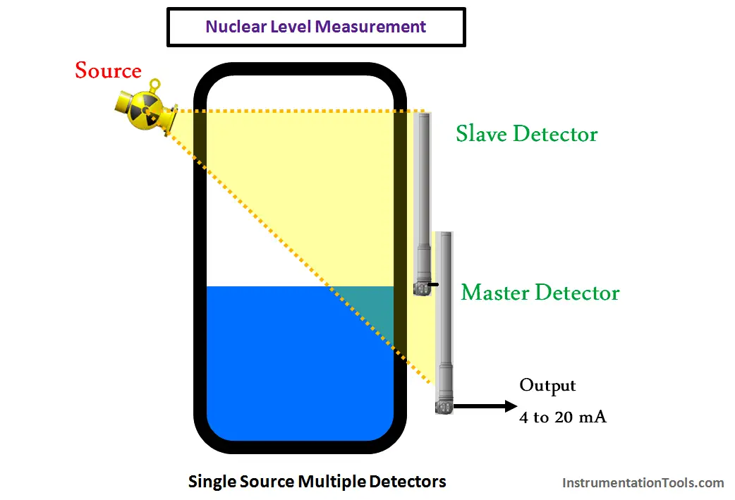
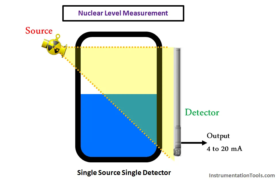
A typical Nuclear / Nucleonic source and detector level measurement is shown in Below Fig 1.

Contents
Single Source – Multiple DetectorsMultiple Source – Multiple DetectorsWiring of master and Slave detectors

Nuclear Level Measurement

Also see : Nuclear Level Detectors Animation

In certain process applications, the vessel or tank level measurements may vary from 2 mtrs to 30 mtrs or more.  In the Nuclear / Nucleonic Level Instruments, detectors are available with standard lengths varying from 2 meter to 6 Meter. Standard length varies from supplier to supplier from 2 mtrs ~ 6 mtrs.

In the case of a larger length of level measurement, multiple detectors will be required, and the detectors need to be connected in cascade mode to cover complete level measurement length of the vessel. Sometimes the single nuclear source may not be able to cover the complete level measurement length, so multiple nuclear sources may be required. This is determined via Nuclear Source strength calculations.

When multiple detectors are used, the same required to be connected in Master-Slave configurations.

The Master detector aggregates (sums up) the signal received from all slave detectors and the output of the master detector corresponds to the total level measurement range of the vessel. The master output is connected to Control System (e.g. DCS) which may be 4-20 mA or serial signal.  A detector located either at Top or at Bottom can be configured as Master Detector based on manufacturer recommendations.

The example shown in the article has master at the bottom.

Single Source – Multiple Detectors

In the below configuration, the nuclear source is single and there are two detectors that cover the level measurement range. Hence there is only one master and one slave detector required.

Nuclear Level DetectorsMultiple Source – Multiple Detectors

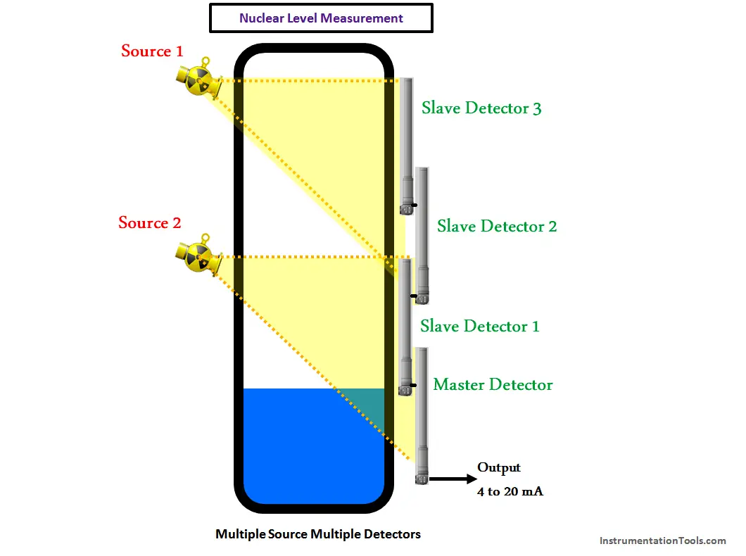
In the below configuration, two no’s nuclear source and four numbers of detectors are required to cover the whole level measurement range. Hence there will be one master and three slave detectors.

Nuclear Level Measurement Multiple Source and Multiple Detectors Principle

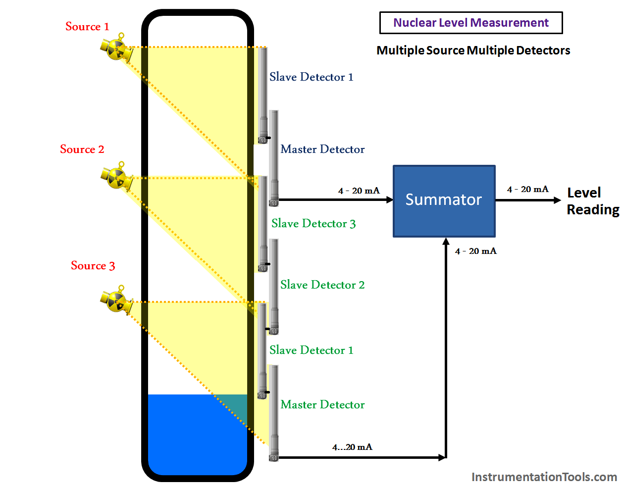
The master detectors have the limitation of maximum no of slave detectors connected (which varies for each supplier); hence we may have to use more than one master detector.

In such cases, both master detectors outputs are connected to a summator device (which may be located at Field or it can be remote) and total output is connected to the DCS system (Below Fig).

Nuclear Level Sensor using Master and Slave

Wiring of master and Slave detectors

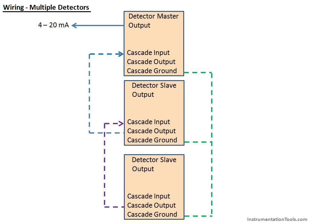
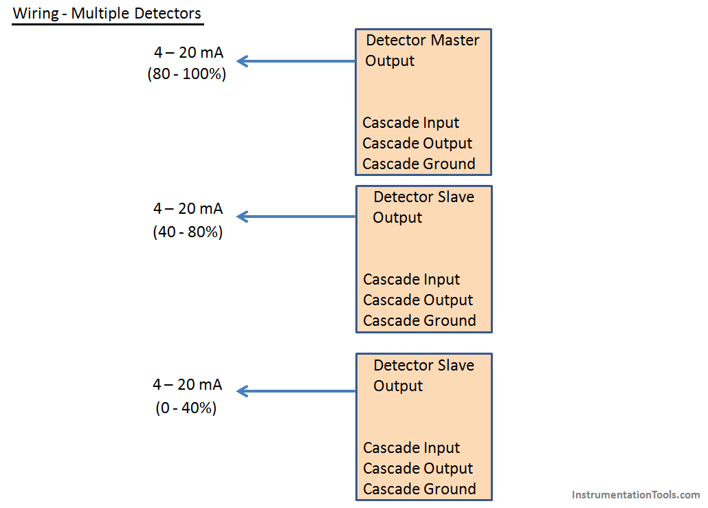
The typical wiring diagram of multiple detectors is shown below. Each detector generally has cascade input, cascade output, cascade ground, and HART output capability. However when detectors are wired in master-slave configurations, then cascade output of slave is connected to cascade input of other slaves.

The master detector 4 -20 mA output is connected to DCS system which will correspond to total level measurement range.

Wiring of Nuclear Level Detectors

In certain cases, the current output (4 ~ 20mA) of each detector is also taken to DCS system and the level measurements are mapped in DCS system to arrive at total level measurement (Below Fig 6).

Nuclear Level Sensors Wiring in Cascade

Also Read : Level Transmitter & Level Gauge Design Tips
Article by :
Nilima singh
Instrumentation and control Engineer
13 year experience in Detail engineering
Worked on various Refinery, Oil & Gas, Petrochemical and chemical projects
Don't Miss Our Updates
Be the first to get exclusive content straight to your email.
We promise not to spam you. You can unsubscribe at any time.
Invalid email address
You've successfully subscribed !

Recommended Articles

Level Transmitter and Level Gauge Design Tips
Servo Level Transmitter Principle
Reversing Control Valve Actuator Fail Safe Mode
Circular Chart Recorder Calibration Procedure
FMCW Radar Level Transmitter Working Principle
Capacitive Level Measurement
Share This Article
Facebook Whatsapp Whatsapp LinkedIn Copy Link
Share
Leave a Comment

Leave a Reply Cancel reply

Your email address will not be published. Required fields are marked *

Stay Connected

128.3kFollowersLike
69.1kFollowersFollow
208kSubscribersSubscribe
38kFollowersFollow

Categories

Recent Comments

  • William Snyder on Top Non-PLC Certification Courses for Automation Professionals
  • Kamli on Top Free PLC Software
  • Guifty Shimica on Top Non-PLC Certification Courses for Automation Professionals
  • Guifty Shimica on Top Non-PLC Certification Courses for Automation Professionals

Related Articles

Non-Contacting-Radar-Level-Transmitter-Animation

Non Contacting Radar Level Transmitter Animation

PLC Program for an Alternate output circuit

PLC Program for Alternate Output Circuit with Latched Function

PLC Program for Automatic Parameter initialization

PLC Program for Automatic Parameter Initialization When Power UP

cat5e plenum cable

cat5e Plenum Cable History, Advantages and Disadvantages

torque tube displacement level transmitter

Level Troll working principle

Slop Tank Level Transmitter Erection

Wrong Installation of Horn Type Radar Level Transmitter on Sloping Tank

Magnetic Float Level Sensor Principle

Magnetic Float Level Transmitter Working Principle

Level Gauge Interface Measurement

Level Gauge Interface & Temperature Problems

More Articles

Electronic Symbols List

Electronic Symbols

Self-balancing Pneumatic Instrument Principles - 3

Self-balancing Pneumatic Instrument Principles

Workstation Healthiness Checks

Workstation Healthiness Checks

Basic PLC Alarm Programming Example

Basic PLC Alarm Programming Example

Solenoid Valve Failure in Plant Start-Up

Solenoid Valve Failure in Plant Start-Up: Identifying the Root Cause

Nonlinear Control Systems

Stability of Nonlinear System – II

Safety Requirement Specifications (SRS) - Safety Instrumented System

Safety Requirement Specifications (SRS) – Safety Instrumented System

Stability in Frequency Domain

Nyquist Stability Criterion

Follow US
All rights reserved. Reproduction in whole or in part without written permission is prohibited.
Welcome Back!

Sign in to your account

Username or Email Address
Password

Lost your password?