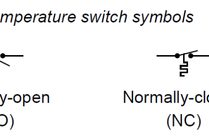
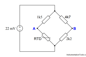
Figure 1 shows a basic bridge circuit which consists of three known resistances, R1, R2, and R3 (variable), an unknown variable resistor RX (RTD), a source of voltage, and a sensitive ammeter.
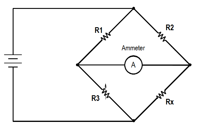
Figure 1 Bridge Circuit
Resistors R1 and R2 are the ratio arms of the bridge. They ratio the two variable resistances for current flow through the ammeter. R3 is a variable resistor known as the standard arm that is adjusted to match the unknown resistor. The sensing ammeter visually displays the current that is flowing through the bridge circuit. Analysis of the circuit shows that when R3 is adjusted so that the ammeter reads zero current, the resistance of both arms of the bridge circuit is the same. The below Equation 1 shows the relationship of the resistance between the two arms of the bridge.
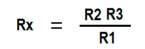
Since the values of R1, R2, and R3 are known values, the only unkown is Rx. The value of Rx can be calulated for the bridge during an ammeter zero current condition. Knowing this resistance value provides a baseline point for calibration of the instrument attached to the bridge circuit. The unknown resistance, Rx, is given by below Equation 2.
Bridge Circuit Operation
The bridge operates by placing Rx in the circuit, as shown in Figure 1, and then adjusting R3 so that all current flows through the arms of the bridge circuit. When this condition exists, there is no current flow through the ammeter, and the bridge is said to be balanced. When the bridge is balanced, the currents through each of the arms are exactly proportional. They are equal if R1 = R2. Most of the time the bridge is constructed so that R1 = R2. When this is the case, and the bridge is balanced, then the resistance of Rx is the same as R3, or Rx = R3.
When balance exists, R3 will be equal to the unknown resistance, even if the voltage source is unstable or is not accurately known. A typical Wheatstone bridge has several dials used to vary the resistance. Once the bridge is balanced, the dials can be read to find the value of R3. Bridge circuits can be used to measure resistance to tenths or even hundredths of a percent accuracy. When used to measure temperature, some Wheatstone bridges with precision resistors are accurate to about + 0.1°F.
Two types of bridge circuits (unbalanced and balanced) are utilized in resistance thermometer temperature detection circuits. The unbalanced bridge circuit (Figure 2) uses a millivoltmeter that is calibrated in units of temperature that correspond to the RTD resistance.
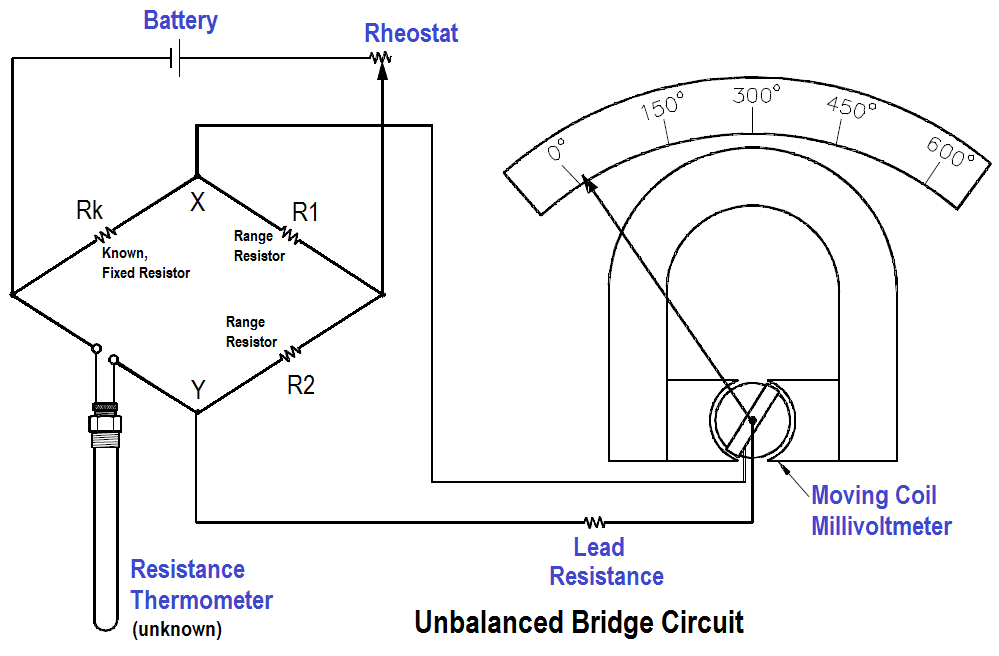
Figure 2 Unbalanced Bridge Circuit
The battery is connected to two opposite points of the bridge circuit. The millivoltmeter is connected to the two remaining points. The rheostat regulates bridge current. The regulated current is divided between the branch with the fixed resistor and range resistor R1, and the branch with the RTD and range resistor R2. As the electrical resistance of the RTD changes, the voltage at points X and Y changes. The millivoltmeter detects the change in voltage caused by unequal division of current in the two branches. The meter can be calibrated in units of temperature because the only changing resistance value is that of the RTD.
The balanced bridge circuit (Figure 3) uses a galvanometer to compare the RTD resistance with that of a fixed resistor. The galvanometer uses a pointer that deflects on either side of zero when the resistance of the arms is not equal. The resistance of the slide wire is adjusted until the galvanometer indicates zero. The value of the slide resistance is then used to determine the temperature of the system being monitored.
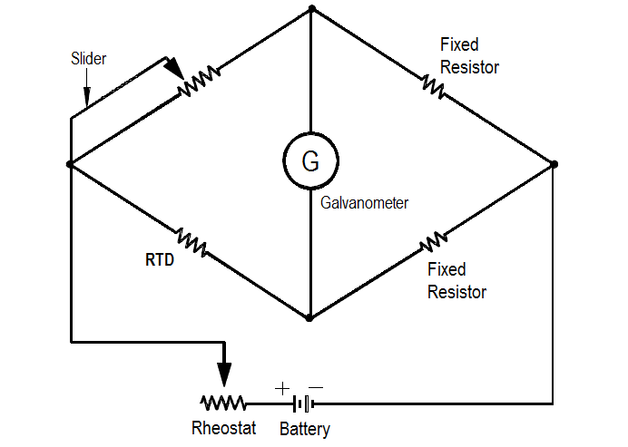
Figure 3 Balanced Bridge Circuit
A slidewire resistor is used to balance the arms of the bridge. The circuit will be in balance whenever the value of the slidewire resistance is such that no current flows through the galvanometer. For each temperature change, there is a new value; therefore, the slider must be moved to a new position to balance the circuit.
Temperature Compensation
Because of changes in ambient temperature, the resistance thermometer circuitry must be compensated. The resistors that are used in the measuring circuitry are selected so that their resistance will remain constant over the range of temperature expected. Temperature compensation is also accomplished through the design of the electronic circuitry to compensate for ambient changes in the equipment cabinet. It is also possible for the resistance of the detector leads to change due to a change in ambient temperature. To compensate for this change, three and four wire RTD circuits are used. In this way, the same amount of lead wire is used in both branches of the bridge circuit, and the change in resistance will be felt on both branches, negating the effects of the change in temperature.
Summary
Temperature detection circuit operation is summarized below.
The basic bridge circuit consists of:
- Two known resistors (R1 and R2) that are used for ratioing the adjustable and known resistances
- One known variable resistor (R3) that is used to match the unknown variable resistor
- One unknown resistor (Rx) that is used to measure temperature
- A sensing ammeter that indicates the current flow through the bridge circuit
The bridge circuit is considered balanced when the sensing ammeter reads zero current.
A basic temperature instrument is comprised of:
- An RTD for measuring the temperature
- A bridge network for converting resistance to voltage
- A DC to AC voltage converter to supply an amplifiable AC signal to the amplifier
- An AC signal amplifier to amplify the AC signal to a usable level
An open circuit in a temperature instrument is indicated by a very high temperature. A short circuit in a temperature instrument is indicated by a very low temperature.
Temperature instrument ambient temperature compensation is accomplished by:
- Measuring circuit resistor selection
- Electronic circuitry design
- Use of three or four wire RTD circuits