Inst ToolsInst ToolsInst Tools
  • Courses
  • Automation
    • PLC
    • Control System
    • Safety System
    • Communication
    • Fire & Gas System
  • Instrumentation
    • Design
    • Pressure
    • Temperature
    • Flow
    • Level
    • Vibration
    • Analyzer
    • Control Valve
    • Switch
    • Calibration
    • Erection & Commissioning
  • Interview
    • Instrumentation
    • Electrical
    • Electronics
    • Practical
  • Q&A
    • Instrumentation
    • Control System
    • Electrical
    • Electronics
    • Analog Electronics
    • Digital Electronics
    • Power Electronics
    • Microprocessor
Search
  • Books
  • Software
  • Projects
  • Process
  • Tools
  • Basics
  • Formula
  • Power Plant
  • Root Cause Analysis
  • Electrical Basics
  • Animation
  • Standards
  • 4-20 mA Course
  • Siemens PLC Course
Reading: Control Valve Working Animation
Share
Notification Show More
Font ResizerAa
Inst ToolsInst Tools
Font ResizerAa
  • Courses
  • Design
  • PLC
  • Interview
  • Control System
Search
  • Courses
  • Automation
    • PLC
    • Control System
    • Safety System
    • Communication
    • Fire & Gas System
  • Instrumentation
    • Design
    • Pressure
    • Temperature
    • Flow
    • Level
    • Vibration
    • Analyzer
    • Control Valve
    • Switch
    • Calibration
    • Erection & Commissioning
  • Interview
    • Instrumentation
    • Electrical
    • Electronics
    • Practical
  • Q&A
    • Instrumentation
    • Control System
    • Electrical
    • Electronics
    • Analog Electronics
    • Digital Electronics
    • Power Electronics
    • Microprocessor
Follow US
All rights reserved. Reproduction in whole or in part without written permission is prohibited.
Inst Tools > Blog > Animation > Control Valve Working Animation

Control Valve Working Animation

Last updated: August 22, 2020 10:08 am
Editorial Staff
Animation Control Valves How It Works
15 Comments
Share
5 Min Read
SHARE

Control valves are valves used to control conditions such as flow, pressure, temperature, and liquid level by fully or partially opening or closing in response to signals received from controllers that compare a “setpoint” to a “process variable” whose value is provided by sensors that monitor changes in such conditions.

Contents
Control Valve Working AnimationWhy Control Valves used?Principles of OperationTypes of control valve bodies

Control Valve is also termed as the Final Control Element.

Control Valve Working Animation

Control Valve Working Animation

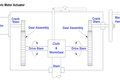
The opening or closing of control valves is usually done automatically by electrical, hydraulic or pneumatic actuators. Positioners are used to control the opening or closing of the actuator based on electric, or pneumatic signals.

These control signals, traditionally based on 3-15psi (0.2 to 1.0 bar), more common now are 4-20mA signals for industry.

Why Control Valves used?

Process plants consist of hundreds, or even thousands, of control loops all networked together to produce a product to be offered for sale.

Each of these control loops is designed to keep some important process variable such as pressure, flow, level, temperature, etc. within a required operating range to ensure the quality of the end product.

Each of these loops receives and internally creates disturbances that detrimentally affect the process variable, and interaction from other loops in the network provides disturbances that influence the process variable.

To reduce the effect of these load disturbances, sensors and transmitters collect information about the process variable and its relationship to some desired set point. A controller then processes this information and decides what must be done to get the process variable back to where it should be after a load disturbance occurs.

When all the measuring, comparing, and calculating are done, some type of final control element must implement the strategy selected by the controller.

Principles of Operation

The most common final control element in the process control industries is the control valve. The control valve manipulates a flowing fluid, such as gas, steam, water, or chemical compounds, to compensate for the load disturbance and keep the regulated process variable as close as possible to the desired set point.

Control valves may be the most important, but sometimes the most neglected, part of a control loop. The reason is usually the instrument engineer’s unfamiliarity with the many facets, terminologies, and areas of engineering disciplines such as fluid mechanics, metallurgy, noise control, and piping and vessel design that can be involved depending on the severity of service conditions.

Any control loop usually consists of a sensor of the process condition, a transmitter and a controller that compares the “process variable” received from the transmitter with the “set point,” i.e., the desired process condition. The controller, in turn, sends a corrective signal to the “final control element,” the last part of the loop and the “muscle” of the process control system.

While the sensors of the process variables are the eyes, the controller the brain, then the final control element is the hands of the control loop. This makes it the most important, alas sometimes the least understood, part of an automatic control system. This comes about, in part, due to our strong attachment to electronic systems and computers causing some neglect in the proper understanding and proper use of the all important hardware.

A control valve consists of three main parts in which each part exist in several types and designs:

  • Valve’s actuator
  • Valve’s positioner
  • Valve’s body

Types of control valve bodies

The most common and versatile types of control valves are sliding-stem globe and angle valves. Their popularity derives from rugged construction and the many options available that make them suitable for a variety of process applications, including severe service.

Control valve bodies may be categorized as below

  • Angle Valves
    • Cage-style valve bodies
    • DiskStack style valve bodies
  • Angle seat piston valves
  • Globe valves
    • Single-port valve bodies
    • Balanced-plug cage-style valve bodies
    • High capacity, cage-guided valve bodies
    • Port-guided single-port valve bodies
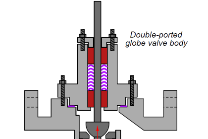
    • Double-ported valve bodies
    • Three-way valve bodies
  • Diaphragm Valves
  • Rotary valves
    • Butterfly valve bodies
    • V-notch ball control valve bodies
    • Eccentric-disk control valve bodies
    • Eccentric-plug control valve bodies
  • Sliding cylinder valves
    • Directional control valve
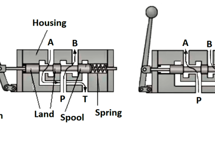
    • Spool valve
    • Piston valve
  • Air-operated valves
    • Air-operated valve
    • Relay valve
    • Air-operated pinch valve

Also Read: Control Valve Characteristics

Don't Miss Our Updates
Be the first to get exclusive content straight to your email.
We promise not to spam you. You can unsubscribe at any time.
Invalid email address
You've successfully subscribed !

Continue Reading

Functional Testing of Control Valve Positioners
ESDV : How it Works ?
Gas chromatograph Working Animation
Current to Pressure (I/P) Converter Principle
How does SMPS Works? – Switched Mode Power Supply
Rotork Motor Operated Valve Basic Configuration
Share This Article
Facebook Whatsapp Whatsapp LinkedIn Copy Link
Share
15 Comments
  • Muralidharan says:
    March 12, 2016 at 5:16 am

    Nice descriptions…

    Reply
  • Kemboi Victor says:
    August 12, 2016 at 1:28 pm

    I like it,well explained and understandable

    Reply
  • Noor Mustafa says:
    August 30, 2016 at 7:32 pm

    very nice

    Reply
  • Vickry Saifuddin says:
    November 24, 2016 at 6:39 am

    I like it, very interesting.

    Reply
  • mahesh says:
    January 9, 2017 at 5:37 am

    Nice

    Reply
  • romeo says:
    January 9, 2017 at 4:44 pm

    very useful
    Thanks for sharing.

    Reply
  • nagulal malkari says:
    January 11, 2017 at 2:00 am

    Very useful

    Reply
  • Eg. Pooran singh says:
    January 31, 2017 at 12:08 pm

    Very good

    Reply
  • Sai kiran says:
    August 9, 2017 at 3:59 pm

    How does that air comes back…

    I mean.. how does the valve take before position..?

    Reply
  • V.D.Haldikar says:
    October 5, 2017 at 7:54 am

    Ah!!
    I like it, that’s the way !

    Reply
  • ankita says:
    December 22, 2017 at 6:24 am

    thanks for the sharing information.

    Reply
  • Jack says:
    February 6, 2018 at 12:59 pm

    Pretty cool and visual! You should’ve participated in the Visaya Solutions article about the subject

    Reply
  • Godswill Nwanne says:
    April 30, 2019 at 4:37 pm

    The Definition and Illustration on Control Valve working principle is clear.
    Tools implemented for Animation demonstration are highly technical.
    Technology is improving, very encouraging.
    Thanks so much.

    Reply
  • BIKAS GHOSH says:
    September 6, 2019 at 12:59 am

    The control valve animation shared is giving a good insight into control valve operation . Thanks for sharing.

    Reply
  • Anandhu says:
    May 21, 2020 at 1:09 pm

    As per the animation it seems to be the valve starts operating at 4 ma how its possible in a 4-20 mA loop??

    Reply

Leave a Reply Cancel reply

Your email address will not be published. Required fields are marked *

Stay Connected

128.3kFollowersLike
69.1kFollowersFollow
208kSubscribersSubscribe
38kFollowersFollow

Categories

Explore More

How to Choose a Control Valve?
Calculate Flow Coefficient Kv of Solenoid Valve
Pressure Safety Valve Leak Test Procedure (PSV Testing)
Direct Acting Control Valves & Reverse Acting Control Valves
Oval Gear Flow Meters – Principle, Advantages, Animation
Level Indicators Working Principle
Difference between PCV and PRV
Control Valve End Connection

Keep Learning

Trip Valve Shown Tripped

Trip Valve Principle

Motor Operated Valve Problems and Troubleshooting

Motor Operated Valve Problems and Troubleshooting

Differential Pressure Switch Working Principle

Valve Diaphragm Actuator

Spring and Diaphragm Pneumatic Actuators

Piston Flow Meters Working Animation

Piston Flow Meters Working Principle with Animation

Two Wire Sensors Animation

Two Wire Sensor Working Principle and Animation

Disk valves

What is a Disc Valve ?

Applications of Tilting Level Switch

How Tilt Level Switch Works ?

Learn More

Resistance Temperature Detectors Troubleshooting Tips

Resistance Temperature Detectors Troubleshooting Tips

Avoid Process Downtime With Five Device Protection Considerations

How to Avoid Process Downtime ?

RF Admittance Level Transmitter Working Principle

RF Admittance Level Transmitter Working Principle

IP Ratings and Equivalent NEMA Ratings

IP Ratings and Equivalent NEMA Ratings

valve trim

Valve Actuator Bench Set

Air Pre-heater

What is an Air Pre-heater? – Types, Working, Advantages

pH and ORP eBook Download

pH and ORP Learning Handbook

Allen-Bradley MicroLogix controller

Programmable Logic Controller (PLC) Questions and Answers – 16

Follow US
All rights reserved. Reproduction in whole or in part without written permission is prohibited.
Welcome Back!

Sign in to your account

Username or Email Address
Password

Lost your password?