Given the ability of pressurized fluids to transmit force over long distances, it is not surprising that many practical “fluid power systems” have been built using fluid as a mechanical power-conducting media. Fluid systems may be broadly grouped into pneumatic (gas, usually air) and hydraulic (liquid, usually oil).
Note: While it would be technically possible to use water instead of oil in a hydraulic power system, oil enjoys some distinct advantages. First, oil is a lubricating substance, and non-corrosive, unlike water. Second, oil enjoys a wider operating temperature range than water, which tends to both freeze and boil more readily.
Although there is no particular reason why a fluid power system must be discrete and not continuous, the majority of fluid power systems operate in an on/off control mode rather than throttling. As usual for technical specialties, fluid power has its own unique symbology for describing various components and their interconnections.
Fluid Power Systems
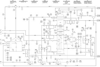
The following diagram shows some common symbols used in fluid power system diagrams. Lines connecting components together in a fluid power diagram indicate pipes, hoses, or tubes, much like lines connecting components together in an electronic schematic diagram represent wires:

Many of these symbols are self-explanatory, especially the pumps, motors, and cylinders. What seems to cause the most confusion for people new to this symbology are the spool valve symbols.
A “spool” valve is a special type of flow-directing valve used in pneumatic and hydraulic systems to direct the pressurized fluid to different locations.
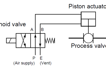
The symbology for a spool valve is a set of boxes, each box containing arrows or other symbols showing the intended direction(s) for the fluid’s travel. Take for instance this pneumatic reversing cylinder control system:

The proper way to interpret a spool valve symbol is to see only one “box” active at any given time. As the actuator (in this case, a hand-actuated lever) is moved one way or the other, the boxes “shift” laterally to redirect the flow of fluid from source to load.
For example, when the spool valve in this reversing control system is in its center position, the outer boxes in the symbol are inactive. This is emphasized in the following diagram by coloring the outer boxes grey.
In this position, the spool valve neither admits compressed air to the cylinder nor vents any air from the cylinder. As a result, the piston within the cylinder holds its position:

If the spool valve is actuated in one direction, the spool piece inside the valve assembly shifts, directing compressed air to one side of the cylinder while venting air from the other side.
This is shown in the following diagram by shifting the boxes to one side, lining up the “active” box with the cylinder and air supply/vent connections:

If the spool valve is actuated in the other direction, the spool piece inside the valve assembly shifts again, switching the directions of air flow to and from the cylinder.
Compressed air still flows from the supply to the vent, but the direction within the cylinder is reversed. This causes the piston to reverse its mechanical travel:

Note that the boxes in a spool valve symbol are never shifted or grayed-out in color like this to represent the valve’s state in a real fluid power diagram.
The previous illustrations were drawn this way only as an aid to your understanding, teaching you how to interpret the meaning of the symbols when you see them in real fluid power diagrams.
Like electrical switches represented in schematic diagrams, spool valve symbols are always drawn with the boxes aligned in their “resting” states, and with all portions identically colored.
Hydraulic systems require more components, including filters and pressure regulators, to ensure proper operation. Shown here is a simple uni-directional hydraulic motor control system:

Note the placement of the pressure relief valve: it is a shunt regulator, bleeding excess pressure from the discharge of the hydraulic pump back to the reservoir.
A “shunt” regulator is necessary because hydraulic pumps are positive displacement, meaning they discharge a fixed volume of fluid with every revolution of the shaft. If the discharge of a positive-displacement pump is blocked (as it would be if the spool valve were placed in its default “off” position, with no shunt regulator to bleed pressure back to the reservoir), it will mechanically “lock” and refuse to turn.
This would overload the electric motor coupled to the pump, if not for the pressure regulating valve providing an alternative route for oil to flow back to the reservoir. This shunt regulator allows the pump to discharge a fixed rate of oil flow (for a constant electric motor speed) under all hydraulic operating conditions.
An alternative to using a shunt regulating valve in a hydraulic system is to use a variable displacement pump. Variable-displacement pumps still output a certain volume of hydraulic oil per shaft revolution, but that volumetric quantity may be varied by moving a component within the pump. In other words, the pump’s per-revolution displacement of oil may be externally adjusted.
If we connect the variable-displacement mechanism of such a hydraulic pump to a pressure sensing element such as a bellows, in a way where the pump senses its own discharge pressure and adjusts its volumetric output accordingly.
we will have a pressure-regulating hydraulic system that not only prevents the pump from “locking” when the spool valve turns off, but also saves energy by not circulating pressurized oil all the time:

Note the placement of a filter at the inlet of the pump in all hydraulic systems. Filtration is an absolute essential for any hydraulic system, given the extremely tight dimensional tolerances of components inside pumps, motors, spool valves, and cylinders.
Even very small concentrations of particulate impurities in the hydraulic fluid may drastically shorten the life of these precision machined components.
Hydraulic fluid also acts as a heat-transfer medium, and as such must be kept cool enough to prevent thermal damage to components. Large hydraulic systems are equipped with coolers, which are just heat exchangers designed to extract heat energy from the fluid and transfer it to either cooling water or ambient air.
Small hydraulic systems dissipate heat at a fast enough rate through their components that coolers are often unnecessary.
An interior view of a simple “2-way” spool valve such as that used in the hydraulic motor system previously examined reveals why cleanliness and temperature stability is important.
The spool valve is shown here in both positions, with its accompanying schematic symbol:

Both the spool and the valve body it moves in are circular in cross-section. The spool has wide areas called “lands” that act to cover and uncover ports in the valve body for fluid to flow through.
The precise fit between the outside diameter of the lands and the inside diameter of the valve body’s bore is the only factor limiting leakage through this spool valve in the closed state.
Dirty hydraulic fluid will wear at this precise fit over time until the valve is no longer capable of sealing fluid in its “closed” position. Extreme cycles in temperature will also compromise the precise fit between the spool and the valve body.
Pneumatic fluid power systems require cleanliness as well, since any particulate contamination in the air will likewise cause undue wear in the close-tolerance compressors, motors, valves, and cylinders.
Unlike hydraulic oil, compressed air is not a natural lubricant, which means many pneumatic power devices benefit from a small concentration of oil vapor in the air.
Pneumatic “oilers” designed to introduce lubricating oil into a flowing air stream are generally located very near the point of use (e.g. the motor or the cylinder) to ensure the oil does not condense and “settle” in the air piping.
Fluid power systems in general tend to be inefficient, requiring much more energy input to the fluid than what is extracted at the points of use.
When large amounts of energy need to be transmitted over long distances, electricity is the a more practical medium for the task. However, fluid power systems enjoy certain advantages over electric power, a few of which are listed here:
- Fluid power motors and cylinders do not overload at low speeds or under locked conditions
- Fluid power systems present little hazard of accidentally igniting flammable atmospheres (i.e. no sparks produced)
- Fluid power systems present little or no fire hazard
- Fluid power systems present no hazard of electric shock or arc flash
- Fluid power systems are often easier to understand and troubleshoot than electric systems
- Fluid power systems may be safely used in submerged (underwater) environments
- Pneumatic systems are relatively easy to equip with back-up energy reserve (e.g. liquefied nitrogen serving as a back-up gas supply in the event of compressor shut-down)
- Pneumatic systems are self-purging (i.e. enclosures housing pneumatic devices will be naturally purged of dusts and vapors by leaking air)
Another important consideration for fluid power systems is the ongoing maintenance work they require for reliable operation. Hydraulic power systems will suffer rapid wear if the hydraulic oil is not clean and chemically stable.
The fluid in a hydraulic system not only transmits mechanical power, but it also lubricates and stabilizes the temperature of components as they transfer that power between different forms.
Regular filter changes and oil changes (especially if the fluid is subject to contamination from the process) is necessary for long service life of any hydraulic system.
Pneumatic (instrument air) systems must be free of water vapor and particulate contamination for much the same reason. Water is perhaps the most common contaminant in instrument air systems, causing corrosion of metal components and subsequent clogging of orifices.
Special devices called air dryers installed in instrument air systems use solid materials called desiccants to absorb water entrained in the compressed air. The desiccant material is “regenerated” by the dryer mechanism on a regular cycle, but must be periodically replaced when its water-absorbing ability wanes.