Inst ToolsInst ToolsInst Tools
  • Ask
  • Courses
  • Videos
  • Q & A
    • Interview
      • Instrumentation
      • Electronics
      • Electrical
      • Practical Questions
    • MCQ
      • Instrumentation MCQ
      • Electrical MCQ
      • Electronics MCQ
      • Control Systems MCQ
      • Analog Electronics MCQ
      • Digital Electronics MCQ
      • Power Electronics MCQ
      • Microprocessor MCQ
      • Multiple Choice Questions
  • EE
    • Electronics
      • Electronics Q & A
      • Electronic Basics
      • Electronic Devices & Circuits
      • Electronics Animation
      • Digital Electronics
    • Electrical
      • Electrical Basics
      • Electrical Q & A
      • Power Electronics
      • Electrical Machines
      • Electrical Animation
      • Power Systems
      • Switchgear & Protection
      • Transmission & Distribution
  • Measure
    • Control Valves
    • Calibration
    • Temperature
    • Pressure
    • Flow
    • Level
    • Analyzers
    • Switches
    • Vibration
    • Solenoid Valve
  • Control
    • PLC Tutorials
    • Control Systems
    • Safety Instrumented System (SIS)
    • Communication
    • Fire & Gas System
  • More
    • Design
    • Tools
    • Animation
    • Basics
    • Formulas
    • Standards
    • TextBooks
    • Common
    • Software
    • Excel Tools
    • Erection & Commissioning
    • Process Fundamentals
    • Videos
    • Books
Search
All rights reserved. Reproduction in whole or in part without written permission is prohibited.
Reading: Snap Acting Relay Working Principle
Share
Notification Show More
Font ResizerAa
Inst ToolsInst Tools
Font ResizerAa
  • Courses
  • PLC Tutorials
  • Control Systems
Search
  • Ask
  • Courses
  • Videos
  • Q & A
    • Interview
    • MCQ
  • EE
    • Electronics
    • Electrical
  • Measure
    • Control Valves
    • Calibration
    • Temperature
    • Pressure
    • Flow
    • Level
    • Analyzers
    • Switches
    • Vibration
    • Solenoid Valve
  • Control
    • PLC Tutorials
    • Control Systems
    • Safety Instrumented System (SIS)
    • Communication
    • Fire & Gas System
  • More
    • Design
    • Tools
    • Animation
    • Basics
    • Formulas
    • Standards
    • TextBooks
    • Common
    • Software
    • Excel Tools
    • Erection & Commissioning
    • Process Fundamentals
    • Videos
    • Books
Follow US
All rights reserved. Reproduction in whole or in part without written permission is prohibited.
Inst Tools > Blog > Control Valves > Snap Acting Relay Working Principle

Snap Acting Relay Working Principle

Last updated: October 3, 2019 11:00 am
Editorial Staff
Control Valves
No Comments
Share
2 Min Read
SHARE

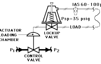
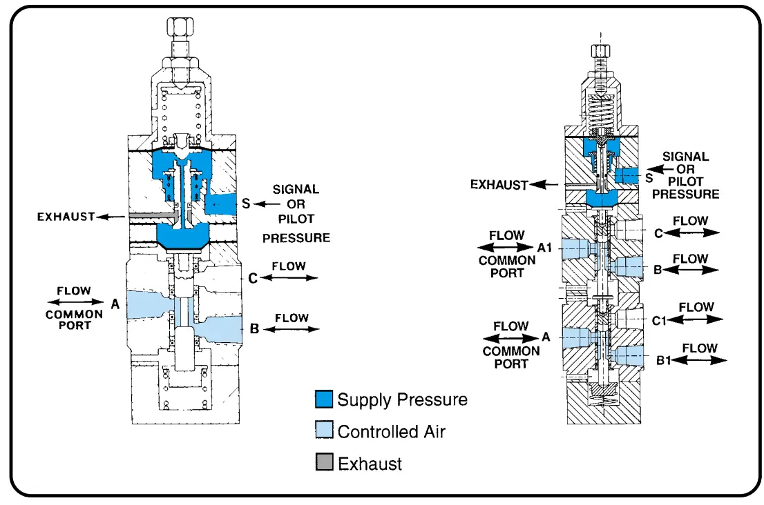
Snap-Acting Relay change ports to switch or lock in secondary air source when the main supply pressure fails below a predetermined set point.

Contents
Snap-Acting RelayArticles You May Like :How Gate Valves Work ?Pressure on Control Valve LiftDouble Acting ActuatorsCage-guided Globe ValveElectric Motor Actuator Parts

In the event of supply or pilot pressure failure, the positive action relay with one common and two inlet or outlet ports will automatically:

  • Switch from main to auxiliary supply pressure
  • Lock an actuator in its last position
  • Extend or retract an actuator stem
  • Divert flow or pressure from one device to another

Snap-Acting Relays have an integral pilot which eliminates the extra piping and connections required with other lock-up valves. Compact and lightweight, the relays are easily piped and mounted.

Snap-Acting Relay

Snap Acting Relay Working Principle

The pressure at which the relays will actuate can be adjusted to any point between 25 PSI (172 kPa) and 85 PSI (586 kPa). Signal or pilot pressure acting in the upper diaphragm overcomes the force of the spring in the bonnet and permits air to flow into the lower chamber.

This pressure buildup forces the spring-loaded spool valve to open common Port “A” to “B”. When the pressure drops below the preset point, the exhaust port opens and common Port “A” is switched from “B” to “C” by releasing the spring loaded spool valve

The spool valve will return to its original position (“A” to “B” when the pressure to the pilot is less than or equal to 20% greater than the set point.

For example, if the set pressure is 50 PSI (345 kPa), the unit will return to its original position when the pressure to the pilot builds up to approximately 60 PSI (414 kPa).

Note : The above mentioned pressures are for reference only, These will change as per make/model.

Source : masonika
Articles You May Like :

How Gate Valves Work ?

Pressure on Control Valve Lift

Double Acting Actuators

Cage-guided Globe Valve

Electric Motor Actuator Parts

Don't Miss Our Updates
Be the first to get exclusive content straight to your email.
We promise not to spam you. You can unsubscribe at any time.
Invalid email address
You've successfully subscribed !
Air Pressure Regulator Questions
How to Install a Control Valve?
Pressure to Current (P/I) Converter Principle
Working Principle of Pneumatic Actuators
What is a Spool Valve? – Types, Configurations, Applications
Share This Article
Facebook Whatsapp Whatsapp LinkedIn Copy Link
Share
Leave a Comment

Leave a Reply Cancel reply

Your email address will not be published. Required fields are marked *

Stay Connected

128.3kFollowersLike
69.1kFollowersFollow
208kSubscribersSubscribe
38kFollowersFollow

Categories

Recent Comments

  • Kamli on Top Free PLC Software
  • Guifty Shimica on Top Non-PLC Certification Courses for Automation Professionals
  • Guifty Shimica on Top Non-PLC Certification Courses for Automation Professionals
  • MIHARITSOA Aina Sitraka on Top Non-PLC Certification Courses for Automation Professionals

Related Articles

How to Do Maintenance of Control Valve Which is Stuck in Field?

How to Do Maintenance of Control Valve Which is Stuck in Field?

Internal Parts of Globe Valve

How to Choose a Control Valve?

Control Valve flow coefficient (Cv)

Why we Measure Control Valve flow coefficient (Cv)?

Control Valve Positioners

Control Valve Positioners

Selecting the Proper Failure Mode

How to Select Control Valve Failure Mode

Difference-between-pneumatic-electric-hydraulic-actuators

Difference between Pneumatic, Electrical & Hydraulic Actuators

Control Valve Calibration

How-to do Control Valve Calibration?

gate-valve-principle-animation

Basics of Gate Valves

More Articles

PIN Diode Working Principle

PIN Diode Working Principle

Simatic Prosave HMI

How to Backup and Restore from Simatic Prosave HMI?

In-Situ Zirconia Oxygen Analyzer

Oxygen (O2) Measurement in Flue Gas

What is Data Acquisition

What is Data Acquisition? – Elements and Components

Infrastructure Monitoring in Your Business Operations

Infrastructure Monitoring in Your Business Operations

Lime Slaker

Advancements in Lime Slaking Technology: What’s New And What’s Next

Open Channel Flow Measurement Animation

Open Channel Flow Measurement Principle

Total Organic Carbon Analyzer Working Principle

TOC Analyzer Working Principle

Follow US
All rights reserved. Reproduction in whole or in part without written permission is prohibited.
Welcome Back!

Sign in to your account

Username or Email Address
Password

Lost your password?