Inst ToolsInst ToolsInst Tools
  • Courses
  • Automation
    • PLC
    • Control System
    • Safety System
    • Communication
    • Fire & Gas System
  • Instrumentation
    • Design
    • Pressure
    • Temperature
    • Flow
    • Level
    • Vibration
    • Analyzer
    • Control Valve
    • Switch
    • Calibration
    • Erection & Commissioning
  • Interview
    • Instrumentation
    • Electrical
    • Electronics
    • Practical
  • Q&A
    • Instrumentation
    • Control System
    • Electrical
    • Electronics
    • Analog Electronics
    • Digital Electronics
    • Power Electronics
    • Microprocessor
  • Request
Search
  • Books
  • Software
  • Projects
  • Process
  • Tools
  • Basics
  • Formula
  • Power Plant
  • Root Cause Analysis
  • Electrical Basics
  • Animation
  • Standards
  • 4-20 mA Course
  • Siemens PLC Course
Reading: What is Cage-guided Globe Valve ?
Share
Font ResizerAa
Inst ToolsInst Tools
Font ResizerAa
  • Courses
  • Design
  • PLC
  • Interview
  • Control System
Search
  • Courses
  • Automation
    • PLC
    • Control System
    • Safety System
    • Communication
    • Fire & Gas System
  • Instrumentation
    • Design
    • Pressure
    • Temperature
    • Flow
    • Level
    • Vibration
    • Analyzer
    • Control Valve
    • Switch
    • Calibration
    • Erection & Commissioning
  • Interview
    • Instrumentation
    • Electrical
    • Electronics
    • Practical
  • Q&A
    • Instrumentation
    • Control System
    • Electrical
    • Electronics
    • Analog Electronics
    • Digital Electronics
    • Power Electronics
    • Microprocessor
  • Request
Follow US
All rights reserved. Reproduction in whole or in part without written permission is prohibited.
Inst Tools > Blog > Control Valves > What is Cage-guided Globe Valve ?

What is Cage-guided Globe Valve ?

Last updated: March 21, 2019 3:15 pm
Editorial Staff
Control Valves
No Comments
Share
4 Min Read
SHARE

A more modern version of the globe valve design uses a piston-shaped plug inside a surrounding cage with ports cast or machined into it.

These cage-guided globe valves throttle flow by uncovering more or less of the port area in the surrounding cage as the plug moves up and down. The cage also serves to guide the plug so the stem need not be subjected to lateral forces as in a stem-guided valve design.

Cage-guided Globe Valve

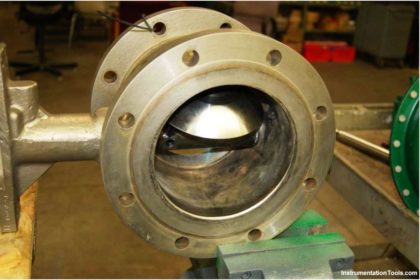
A photograph of a cut-away control valve shows the appearance of the cage (in this case, with the plug in the fully closed position). Note the “T”-shaped ports in the cage, through which fluid flows as the plug moves up and out of the way:

cut-away control valve

An advantage of the cage-guided design is that the valve’s flowing characteristics may be easily altered just by replacing the cage with another having different size or shape of holes.

By contrast, stem-guided and port-guided globe valves are characterized by the shape of the plug, which requires further disassembly to replace than the cage in a cage-guided globe valve.

With most cage-guided valves all that is needed to replace the cage is to separate the bonnet from the rest of the valve body, at which point the cage may be lifted out of the body and swapped with another cage.

In order to change a globe valve’s plug, you must first separate the bonnet from the rest of the body and then de-couple the plug and plug stem from the actuator stem, being careful not to disturb the packing inside of the bonnet as you do so.

After replacing a plug, the “bench-set” of the valve must be re-adjusted to ensure proper seating pressure and stroke calibration.

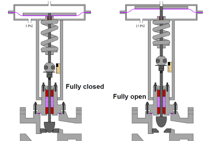
Cage-guided globe valves are available with both balanced and unbalanced plugs. A balanced plug has one or more ports drilled from top to bottom, allowing fluid pressure to equalize on both sides of the plug. This helps minimize the forces acting on the plug which must be overcome by the actuator:

Cage-guided globe valves

Unbalanced plugs generate a force equal to the product of the differential pressure across the plug and the plug’s area (F = PA), which may be quite substantial in some applications.

Balanced plugs do not generate this same force because they equalize the pressure on both sides of the plug, however, they exhibit the disadvantage of one more leak path when the valve is in the fully closed position (through the balancing ports, past the piston ring, and out the cage ports):

Cage-guided globe valves principle

Thus, balanced and unbalanced cage-guided globe valves exhibit similar characteristics to double ported and single-ported stem- or port-guided globe valves, and for similar reasons.

Balanced cage guided valves are easy to position, just like double-ported stem-guided and port-guided globe valves.

However, balanced cage-guided valves tend to leak more when in the shut position due to a greater number of leak paths, much the same as with double-ported stem-guided and port-guided globe valves.

Don't Miss Our Updates
Be the first to get exclusive content straight to your email.
We promise not to spam you. You can unsubscribe at any time.
Invalid email address
You've successfully subscribed !

Continue Reading

Pneumatic Valve Positioner Working Principle
Basics of Globe Valves
Self-Actuated Valves, Pneumatic & Hydraulic Actuators
Ball Valve Material Selection
What is a Boiler Pressure Relief Valve?
The Replacement Procedure for Control Valve Stem Packing
Share This Article
Facebook Whatsapp Whatsapp LinkedIn Copy Link
Share
Leave a Comment

Leave a Reply Cancel reply

Your email address will not be published. Required fields are marked *

Stay Connected

128.3kFollowersLike
69.1kFollowersFollow
210kSubscribersSubscribe
38kFollowersFollow

Categories

Explore More

How Sliding Stem Valves Work ?
Compare Solenoid Valve Manual Reset and Solenoid Manual Override
Solenoid Valve Working Animation
Calculate Control Valve Stem Position
Basics of Control Valves
How to Solve On-Off Valve Problems?
Four Way Solenoid Valve Working Principle
Free Control Valves Course

Keep Learning

What is Blowdown Valve (BDV)

What is Blowdown Valve (BDV)?

Difference Between Solenoid Valve and Motorized Valve

Difference Between Solenoid Valve and Motorized Valve

How to Protect Pumps from Cavitation

How to Protect Pumps from Cavitation? – Reasons, Solutions

Valve Seat leakage Test

Valve Seat Leakage Test

Difference-between-pneumatic-electric-hydraulic-actuators

Difference between Pneumatic, Electrical & Hydraulic Actuators

The Control Valve Stroke Test Procedure

Control Valve Stroke Test Procedure

Breather Valve Working Principle

Breather Valve Working Principle

Emergency Block Valve

SIS Emergency Block Valves (EBV)

Learn More

Density-Measurement-using-DP-Transmitter-for-open-tank

Density Measurement for Open Tank with Constant Level Application

Reformer Tube Stress Relief Reusable Furnace

Miscellaneous Electrical Tasks – Repaired Reformer Tubes Weld Stress Relief

Globe Valve Disk and Stem Connections

Globe Valve Seat and Disk

Explain What these Spool Valve Represent

Explain What these Spool Valve Symbols Represent?

Strain Gauge Pressure Transducer

Resistance Type Pressure Transducers Principle

Pressure Transmitter Troubleshooting Tips

Pressure Transmitter Troubleshooting Tips

Reed Switch Principle

Reed switch Working Principle

Firmware Version in Siemens PLC

What is the Firmware Version of a PLC? – Siemens PLC Hardware

Menu

  • About
  • Privacy Policy
  • Copyright

Quick Links

  • Learn PLC
  • Helping Hand
  • Part Time Job

YouTube Subscribe

Follow US
All rights reserved. Reproduction in whole or in part without written permission is prohibited.
Welcome Back!

Sign in to your account

Username or Email Address
Password

Lost your password?