Inst ToolsInst ToolsInst Tools
  • Courses
  • Automation
    • PLC
    • Control System
    • Safety System
    • Communication
    • Fire & Gas System
  • Instrumentation
    • Design
    • Pressure
    • Temperature
    • Flow
    • Level
    • Vibration
    • Analyzer
    • Control Valve
    • Switch
    • Calibration
    • Erection & Commissioning
  • Interview
    • Instrumentation
    • Electrical
    • Electronics
    • Practical
  • Q&A
    • Instrumentation
    • Control System
    • Electrical
    • Electronics
    • Analog Electronics
    • Digital Electronics
    • Power Electronics
    • Microprocessor
  • Request
Search
  • Books
  • Software
  • Projects
  • Process
  • Tools
  • Basics
  • Formula
  • Power Plant
  • Root Cause Analysis
  • Electrical Basics
  • Animation
  • Standards
  • 4-20 mA Course
  • Siemens PLC Course
Reading: What is Reducing Valve ?
Share
Notification Show More
Font ResizerAa
Inst ToolsInst Tools
Font ResizerAa
  • Courses
  • Design
  • PLC
  • Interview
  • Control System
Search
  • Courses
  • Automation
    • PLC
    • Control System
    • Safety System
    • Communication
    • Fire & Gas System
  • Instrumentation
    • Design
    • Pressure
    • Temperature
    • Flow
    • Level
    • Vibration
    • Analyzer
    • Control Valve
    • Switch
    • Calibration
    • Erection & Commissioning
  • Interview
    • Instrumentation
    • Electrical
    • Electronics
    • Practical
  • Q&A
    • Instrumentation
    • Control System
    • Electrical
    • Electronics
    • Analog Electronics
    • Digital Electronics
    • Power Electronics
    • Microprocessor
  • Request
Follow US
All rights reserved. Reproduction in whole or in part without written permission is prohibited.
Inst Tools > Blog > Control Valves > What is Reducing Valve ?

What is Reducing Valve ?

Last updated: March 21, 2019 3:40 pm
Editorial Staff
Control Valves
No Comments
Share
4 Min Read
SHARE

Reducing valve automatically reduce supply pressure to a pre-selected pressure as long as the supply pressure is at least as high as the selected pressure.

Contents
Reducing ValveNon-variable Reducing Valve

Reducing Valve

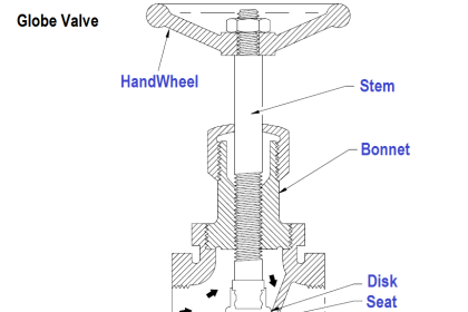
As illustrated in Figure, the principal parts of the reducing valve are the main valve; an upward-seating valve that has a piston on top of its valve stem, an upward-seating auxiliary (or controlling) valve, a controlling diaphragm, and an adjusting spring and screw.

Reducing Valve Parts

Figure : Variable Reducing Valve

Reducing valve operation is controlled by high pressure at the valve inlet and the adjusting screw on top of the valve assembly.

The pressure entering the main valve assists the main valve spring in keeping the reducing valve closed by pushing upward on the main valve disk.

However, some of the high pressure is bled to an auxiliary valve on top of the main valve. The auxiliary valve controls the admission of high pressure to the piston on top of the main valve.

The piston has a larger surface area than the main valve disk, resulting in a net downward force to open the main valve. The auxiliary valve is controlled by a controlling diaphragm located directly over the auxiliary valve.

The controlling diaphragm transmits a downward force that tends to open the auxiliary valve. The downward force is exerted by the adjusting spring, which is controlled by the adjusting screw.

Reduced pressure from the main valve outlet is bled back to a chamber beneath the diaphragm to counteract the downward force of the adjusting spring. The position of the auxiliary valve, and ultimately the position of the main valve, is determined by the position of the diaphragm.

The position of the diaphragm is determined by the strength of the opposing forces of the downward force of the adjusting spring versus the upward force of the outlet reduced pressure.

Other reducing valves work on the same basic principle, but may use gas, pneumatic, or hydraulic controls in place of the adjusting spring and screw.

Non-variable Reducing Valve

Non-variable reducing valves, illustrated in below Figure, replace the adjusting spring and screw with a pre-pressurized dome over the diaphragm.

The valve stem is connected either directly or indirectly to the diaphragm. The valve spring below the diaphragm keeps the valve closed.

As in the variable valve, reduced pressure is bled through an orifice to beneath the diaphragm to open the valve. Valve position is determined by the strength of the opposing forces of the downward force of the pre-pressurized dome versus the upward force of the outlet-reduced pressure.

 What is Non-variable reducing valve

Figure : Non-Variable Reducing Valve

Non-variable reducing valves eliminate the need for the intermediate auxiliary valve found in variable reducing valves by having the opposing forces react directly on the diaphragm.

Therefore, non-variable reducing valves are more responsive to large pressure variations and are less susceptible to failure than are variable reducing valves.

Articles You May Like :

Valve Interview Questions

Hydraulic Actuators

Disassembly of Valve

Control Valve characteristics

What is ON/OFF valve ?

Don't Miss Our Updates
Be the first to get exclusive content straight to your email.
We promise not to spam you. You can unsubscribe at any time.
Invalid email address
You've successfully subscribed !

Continue Reading

Root Cause Analysis for Tank Overflow due to Valve Problem
Pneumatic Control Valve Actuators
Basic Steps and Procedure for the Repair of Control Valve
How is Pressure Drop Calculated through a Valve ?
Why we Require Dual SOV on a Control Valve?
Control Valve Positioners
Share This Article
Facebook Whatsapp Whatsapp LinkedIn Copy Link
Share
Leave a Comment

Leave a Reply Cancel reply

Your email address will not be published. Required fields are marked *

Stay Connected

128.3kFollowersLike
69.1kFollowersFollow
210kSubscribersSubscribe
38kFollowersFollow

Categories

Explore More

Basics of Control Valve Sizing
Identify Valve Parts Quiz with Answers
Control Valves Leakage Classifications
Dampers and Louvres
How Gate Valves Work ?
Self Actuated Pressure Control Valve Functional Testing
What is Complementary Split Range Control (CSRC)?
Inspection and Test Requirement of Control Valves

Keep Learning

Pilot operated Solenoid Valve Principle

How Pilot operated Solenoid Valve Works ?

Rotary Stem Valves

Rotary Stem Valves

PRV

Direct-actuated Safety and Relief Valves

Control Valve Packing

Control Valve Packing

What is Pump Cavitation

What is Pump Cavitation? How to Avoid Cavitation?

solenoid-valves-types-principle-animation

Solenoid Valves Types, Principle & Animation

actuated-valve-schematic

Components of Shutdown Valve

Control Valves Classification

Classification of Control Valves

Learn More

Limit Switches Wiring

Draw Limit Switch Symbol ?

Compare Servo Motor and Stepper Motor

Compare Servo Motor and Stepper Motor

4-Wire, Three-Phase Delta Wiring System

4-Wire, Three-Phase Delta Wiring System

Comparison of Proportional Integral Derivative Controllers (PID)

Comparison of Proportional Integral Derivative Controllers (PID)

self-operated pressure regulating valve

Working Principle of Self Operated Valves

Allen-Bradley MicroLogix 1000 PLC

Questions on Allen-Bradley MicroLogix 1000 PLC

How Buoyant Force instruments Works

How Buoyant Force instruments Works ?

BACNet Protocol

What is the BACNet Protocol? BACNet IP vs. BACNet MS/TP

Menu

  • About
  • Privacy Policy
  • Copyright

Quick Links

  • Learn PLC
  • Helping Hand
  • Part Time Job

YouTube Subscribe

Follow US
All rights reserved. Reproduction in whole or in part without written permission is prohibited.
Welcome Back!

Sign in to your account

Username or Email Address
Password

Lost your password?