Inst ToolsInst ToolsInst Tools
  • Courses
  • Automation
    • PLC
    • Control System
    • Safety System
    • Communication
    • Fire & Gas System
  • Instrumentation
    • Design
    • Pressure
    • Temperature
    • Flow
    • Level
    • Vibration
    • Analyzer
    • Control Valve
    • Switch
    • Calibration
    • Erection & Commissioning
  • Interview
    • Instrumentation
    • Electrical
    • Electronics
    • Practical
  • Q&A
    • Instrumentation
    • Control System
    • Electrical
    • Electronics
    • Analog Electronics
    • Digital Electronics
    • Power Electronics
    • Microprocessor
  • Request
Search
  • Books
  • Software
  • Projects
  • Process
  • Tools
  • Basics
  • Formula
  • Power Plant
  • Root Cause Analysis
  • Electrical Basics
  • Animation
  • Standards
  • 4-20 mA Course
  • Siemens PLC Course
Reading: Working Principle of Flow Switch with Animation
Share
Font ResizerAa
Inst ToolsInst Tools
Font ResizerAa
  • Courses
  • Design
  • PLC
  • Interview
  • Control System
Search
  • Courses
  • Automation
    • PLC
    • Control System
    • Safety System
    • Communication
    • Fire & Gas System
  • Instrumentation
    • Design
    • Pressure
    • Temperature
    • Flow
    • Level
    • Vibration
    • Analyzer
    • Control Valve
    • Switch
    • Calibration
    • Erection & Commissioning
  • Interview
    • Instrumentation
    • Electrical
    • Electronics
    • Practical
  • Q&A
    • Instrumentation
    • Control System
    • Electrical
    • Electronics
    • Analog Electronics
    • Digital Electronics
    • Power Electronics
    • Microprocessor
  • Request
Follow US
All rights reserved. Reproduction in whole or in part without written permission is prohibited.
Inst Tools > Blog > Animation > Working Principle of Flow Switch with Animation

Working Principle of Flow Switch with Animation

Flow Switch operating principle is based on a free-floating magnetic piston that responds only to the motion of fluids within the pipeline.

Last updated: October 31, 2023 12:28 pm
Editorial Staff
Animation Flow Measurement How It Works Switches
7 Comments
Share
2 Min Read
SHARE

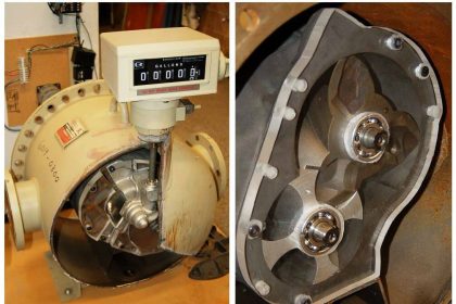
The Flow Switch operating principle is based on a free-floating magnetic piston that responds only to the motion of fluids within the pipeline, not to static or system pressures.

In the presence of fluid flow, controlled movement of the piston actuates an external hermetically sealed reed switch. This switch can be used to actuate audible or visual alarms, as well as relays, or other controls.

The piston’s movement by the fluid flow can be seen in the animation

Flow Switch Animation

Flow Switch Working Principle Animation

flow switches are used to determine if the flow rate is above or below a certain flow rate. This value (the set point) can be fixed or adjustable. When the set point is reached, the response can be the actuation of an electric circuit.

When the flow switch is actuated, it will stay in that condition until the flow rate moves back from the set point by some amount.

If you liked this article, then please subscribe to our YouTube Channel for Instrumentation, Electrical, PLC, and SCADA video tutorials.

You can also follow us on Facebook and Twitter to receive daily updates.

Read Next:

  • Animation of Level Switch
  • Piston Type Pressure Gauge
  • How to Select Rotameter?
  • Paddle Wheel Meter Theory
  • What is a Restriction Orifice?
Don't Miss Our Updates
Be the first to get exclusive content straight to your email.
We promise not to spam you. You can unsubscribe at any time.
Invalid email address
You've successfully subscribed !

Continue Reading

Why Flow is Directly Proportional to the Square Root of DP?
Label the Electrical Circuit Schematic
How does an Orifice Measures Flow?
Dall Tube Flow Meter – Principle, Advantages, Disadvantages
Differential Pressure Switch Working Principle
How to Select a Rotameter? – Parameters and Applications
Share This Article
Facebook Whatsapp Whatsapp LinkedIn Copy Link
Share
7 Comments
  • Josh Koikkara says:
    September 24, 2015 at 1:36 pm

    Sir, using flow switch can we measure flow pressure?

    Reply
    • S Bharadwaj Reddy says:
      September 24, 2015 at 1:51 pm

      Not Possible. Mainly Flow switch used to identify the presence of flow in the pipe.

      Reply
  • kumar says:
    September 24, 2015 at 11:43 pm

    Thanks for sharing the animations.

    Reply
  • Ganesh says:
    February 28, 2016 at 5:43 pm

    Thank u …

    Reply
  • Kamleshwar Rao says:
    March 22, 2016 at 1:24 pm

    How can we use the flow switch mechanism with L&T MU-G10 starter panel to stop the motor on dry run i.e. when there is no flow of water, inorder to stop the motor from dry running.

    Reply
  • Vignesh says:
    July 23, 2016 at 5:42 am

    Easy to understand with your animation. Keep it up.

    Reply
  • ajay singh tomar says:
    December 21, 2016 at 12:47 am

    What is the diff b/n rising and falling setpoint.

    Reply

Leave a Reply Cancel reply

Your email address will not be published. Required fields are marked *

Stay Connected

128.3kFollowersLike
69.1kFollowersFollow
210kSubscribersSubscribe
38kFollowersFollow

Categories

Explore More

Electro-Magnetic Flow meter Objective Questions
What is Integral Flow Orifice Assembly?
Pull Cord Switch Working Principle
How Limit Switch Works ?
Overview of Proximity Switches
Displacer Level Switch Working Principle
Rotameter Working Principle and Animation
Resistance Temperature Detectors Working Principle

Keep Learning

Pneumatic Actuators Types Animation

Types of Pneumatic Actuators Animation

Variable Area Flow Meters

All About Variable Area Flow Meters

Coriolis Mass Flowmeter Principle

Coriolis Mass Flow Sensor Theory

Hydrostatic Level Measurement

Hydrostatic Level Measurement

Turbine Flow Meters Working Animation

Turbine Flow Meters Animation

Comparison of Venturi and Orifice flow meterComparison of Venturi and Orifice flow meter

Comparison of Venturi and Orifice flow meter

positive displacement flow meter pictures

What is a Positive Displacement Flow Meter?

Impulse line - Purpose & Tapping Point Location

Impulse Line – Purpose & Tapping Point Location

Learn More

PLC Instruction List Example for Level Control of Tank

PLC Instruction List Example for Level Control of Tank

Air Pressure Regulator cut-away diagram

Air Pressure Regulator Questions

Project Planning and Implementation of PLC or DCS Control System

Project Planning and Implementation of PLC or DCS Control System

Code Simulation of Safety Circuit

Feedback Monitoring in Safety PLC

Siemens PLC Force LED

Forcing and Modifying PLC Logic

FIFO in STL Language in Siemens PLC

How to Code a FIFO Queue in STL Language in Siemens PLC?

pH Analyzer Calibration and Troubleshooting

pH Analyzer Calibration and Troubleshooting

Cyclic Interrupts TIA Portal

Configuring and Usage of Cyclic Interrupts TIA Portal (OB 30+)

Menu

  • About
  • Privacy Policy
  • Copyright

Quick Links

  • Learn PLC
  • Helping Hand
  • Part Time Job

YouTube Subscribe

Follow US
All rights reserved. Reproduction in whole or in part without written permission is prohibited.
Welcome Back!

Sign in to your account

Username or Email Address
Password

Lost your password?