It is so called because the instrument employs the Coriolis principle which states that “A body of mass M, moving with constant linear velocity, and subject to an angular velocity, (or vibrating) experiences an inertial force at right angles to the direction of motion”. It can be expressed as, Coriolis force = 2Mwv.
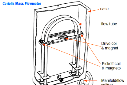
Coriolis Mass Flow Sensor

During operation, a drive coil, located at the center of the bend in the tube, is energized periodically and causes the sensor tube to oscillate (move up and down) about the support axis as shown in the figure above.
The tube vibrates rapidly at a rate of 40-200 cycles per second and through a distance of just a few hundredths of a centimeter.

When there is no flow, as the tube oscillates around the support axis, points I, C, and O move together, reaching the furthest extent of their upward and downward travel at the same time.
When fluid starts to flow through the sensor tube, the tube would be seen to twist around the twist axis, which is perpendicular to the support axis, as shown in the figures below.

Points I, C, and O move up and down like before but C would lag somewhat behind O, and I would lag somewhat behind C.
During the upward half of the cycle (in the right figure), O would have reached the end of its upward travel and begun to move downward before C had reached its upward limit, and I would not reach its upper limit until C had already begun its downward motion.
Also See: Coriolis Flow Meter Animation
The lag between I and O, measured in units of time, is referred to as Δt. This Δt is directly proportional to the mass flow rate of the liquid; the larger the measured value of Δt, the greater the mass flow rate.
The Coriolis sensor will detect this time difference and convert it into a standard signal for the measurement. Voltage is induced at the pickoff coils, located at both sides of the flow tube, based on Faraday’s Law. These coils will have the same amount of induced voltage but with time, they vary with flow rate.
This can be shown in the plotted sine-wave graph; induced voltage (at pickoff coil) vs time as below;

When there is no flow, the sine waves generated by the inlet and outlet sensors are in phase, since the inlet and outlet sides of the tubes have the same velocity.
If superimposed on one another, like in the figure above, the sine waves generated by the outlet side pickoff (C1) and inlet side pickoff (C2) coincide exactly.

When there is flow in the tubes, the sine waves are out of phase. The reason is that the inlet sides of the tubes (C2) are lagging behind the outlet sides (C1).
The amount of time that elapses between the moment when C1 reaches its peak and the moment when C2 reaches its peak is at Δt, the value that we know to be proportional to the mass flow rate.
Because each coil and magnet is also a position sensor, the same sine wave signal also represents the periods of oscillation of the tubes, that is, the time taken for the tubes to make a complete oscillation.
This value τ , provides the basis for density measurement. To represent τ , only one signal is required, as shown in the figure below;

If we begin timing at a zero crossing of the wave and record the elapsed time at the next zero crossing, we will have the tube period and the same can be used to calculate the mass flow rate through the tubes.
If you liked this article, then please subscribe to our YouTube Channel for Instrumentation, Electrical, PLC, and SCADA video tutorials.
You can also follow us on Facebook and Twitter to receive daily updates.
Read Next:
- Advantages of Flow Meter
- Magnetic Flow Meter Corrosion
- What is an Orifice Flange?
- Displacement Flowmeters
- What is a Dall Tube Flowmeter?


How much flow tubes are there?what is mean by sensor tube?
Please, I want to know exactly why the reading from barton chart recorder at gas supply company to be different from reading obtained from ABB totalflow connected with flosic600
whether different for installation this type for gas and liquid? i mean the position of tube (upwards or downward).
Yes, For Liquid : downward installation & For Gas ; Upward installation.
How to check drive coil work or not