THERMOCOUPLES
A thermocouple is made up of two dissimilar metals, joined together at one end, that produce a voltage (expressed in millivolts) with a change in temperature. The junction of the two metals, called the sensing junction, is connected to extension wires. Any two dissimilar metals may be used to make a thermocouple.
Principle of Operation
- When two dissimilar metals are connected together, a small voltage called a thermo-junction voltage is generated at the junction. This is called the Peltier effect.
- If the temperature of the junction changes, it causes voltage to change too, which can be measured by the input circuits of an electronic controller. The output is a voltage proportional to the temperature difference between the junction and the free ends. This is called the Thompson effect.
- Both of these effects can be combined to measure temperature. By holding one junction at a known temperature (reference junction) and measuring the voltage, the temperature at the sensing junction can be deduced. The voltage generated is directly proportional to the temperature difference. The combined effect is known as the thermo-junction effect or the Seebeck effect.
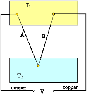
Figure right side illustrates a simple thermocouple circuit.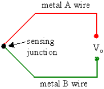
The voltage is measured to infer the temperature. In practical operation, wires A and B are connected to a digital voltmeter (DVM), digital multimeter (DMM), digital data acquisition system, or some other voltage measuring device. If the measuring device has very high input impedance, the voltage produced by the thermo-junction can be measured accurately.
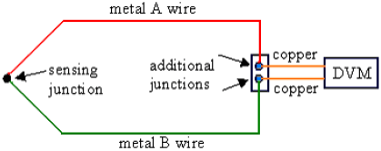
However, the main problem with thermocouple temperature measurement is that wires A and B must connect to the leads of the voltmeter, which are generally made of copper. If neither wire A nor wire B is itself copper, connecting to the DVM creates two more thermo-junctions! (Thermocouple metals are typically not the same as those of the DVM leads.) These additional thermo-junctions also produce a thermo-junctive voltage, which can create an error when trying to measure the voltage from the sensing junction.
How can this problem be resolved?
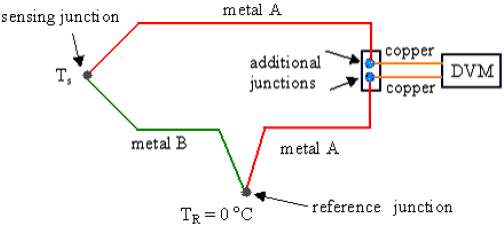
One simple solution is to add a fourth thermo-junction, called a reference junction, by inserting an additional length of metal A wire into the circuit as sketched below. The reference junction consists of metals A and B as indicated on the sketch.
This modified circuit is analyzed as follows:
With this arrangement, there are still two additional thermocouple junctions formed where the compensated thermocouple is connected to the voltmeter (DVM). The two junctions to the DVM are now both between metal A and copper. These two junctions are placed close together , and at the same temperature, so that their thermo-junction voltages are identical, and cancel each other out. Meanwhile, the new reference junction is placed in a location where the reference temperature TR is known accurately, typically in an ice-water bath with a fixed temperature of T R = 0°C. If the sensing junction is also at 0°C (Ts = 0 oC), the voltage generated by the sensing junction will be equal and opposite of that generated by the reference junction. Hence, Vo = 0 when Ts = 0°C. However, if the sensing junction temperature is not equal to TR, Vo will be non-zero.
In summary, Vo is a unique function of the sensor temperature Ts and the two metals used for the thermocouple. Thus, for known reference temperature and known thermocouple wire materials, output voltage Vo can be used to measure temperature. This is the fundamental concept of thermocouple usage.
Thermocouple Materials
Thermocouples may be constructed of several different combinations of materials. The performance of a thermocouple material is generally determined by using that material with platinum. The most important factor to be considered when selecting a pair of materials is the “thermoelectric difference” between the two materials. A significant difference between the two materials will result in better thermocouple performance.
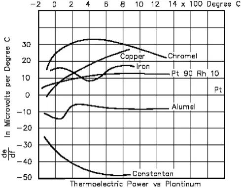
Figure below illustrates the characteristics of the more commonly used materials when used with platinum. For example: Chromel-Constantan is excellent for temperatures up to 2000°F; Nickel/Nickel- Molybdenum sometimes replaces Chromel- Alumel; and Tungsten-Rhenium is used for temperatures up to 5000°F. Some combinations used for specialized applications are Chromel-White Gold, Molybdenum-Tungsten, Tungsten-Iridium, and Iridium/Iridium-Rhodium.
The figure below illustrates the thermocouple material characteristics when used with Platinum.
Characteristics of Thermocouple Types
Of the infinite number of thermocouple combinations, the Instrument Society of America (ISA) recognizes 12. Most of these thermocouple types are known by a single-letter designation; the most common are J, K, T, and E. The compositions of thermocouples are international standards, but the color codes of their wires are different. For example, in the U.S. the negative lead is always red, while the rest of the world uses red to designate the positive lead. Often, the standard thermocouple types are referred to by their trade names. For example,
- A type K thermocouple has the color yellow, and uses chromel – alumel, which are the trade names of the Ni-Cr and Ni-Al wire alloys.
- A type J thermocouple has the color black, and uses iron and constantan as its component metals. (Constantan is an alloy of nickel and copper.)
- A type T thermocouple has the color blue, and uses copper and constantan as its component metals.
- A type S thermocouple uses Pt/Rh-Pt
- A type E thermocouple uses Ni/Cr-Con
- A type N thermocouple uses Ni/Cr/Si-Ni/Si
Each calibration has a different temperature range and environment, although the maximum temperature varies with the diameter of the wire used in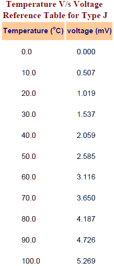 the thermocouple. Variations in the alloy composition and the condition of the junction between the wires are sources of error in temperature measurements. The standard error of thermocouple wire varies from ±0.8 °C to ±4.4 °C, depending on the type of thermocouple used. The K type thermocouple is recommended for most general purpose applications. It offers a wide temperature range, low standard error, and has good corrosion resistance. In fact, many digital multimeters (DMMs) can measure temperature by plugging in a type K thermocouple with standard connections.
The voltage produced by a thermocouple varies almost, but not exactly, linearly with temperature. Therefore, there are no simple equations to relate thermocouple voltage to temperature. Rather, voltage is tabulated as a function of temperature for the various standard thermocouples. In order to convert the millivolt reading to its corresponding temperature, you must refer to tables like the one shown below. These tables can be obtained from the thermocouple manufacturer, and they list the specific temperature corresponding to a series of millivolt readings. By convention, the reference temperature for thermocouple tables is 0ºC.
Choosing a thermocouple type
Because thermocouples measure in wide temperature ranges and can be relatively rugged, they are very often used in industry.
The following criteria are used in selecting a thermocouple:
- Temperature range.
- Chemical resistance of the thermocouple or sheath material.
- Abrasion and vibration resistance.
- Installation requirements (may need to be compatible with existing equipment; existing holes may determine probe diameter).
Standard Specifications
Diameters: Standard diameters: 0.010″, 0.020″, 0.032″, 0.040″, 1/16″, 1/8″, 3/16″, and 1/4″ with two wires.
Length: Standard thermocouples have 12 inch immersion lengths. Other lengths are custom made.
Sheaths: 304 stainless steel and Inconel are standard.
Insulation: Magnesium Oxide is standard. Minimum insulation resistance wire to wire or wire to sheath is 1.5megohms at 500 volts dc in all diameters.
Calibration: Iron-Constantan (J), chromel – alumel (K), Copper-Constantan (T), and Chromel-Constantan (E) are standard calibrations.
Bending: Easily bent and formed. Bend radius should be not less than twice the diameter of the sheath.
Polarity: In the thermocouple industry, standard practice is to color the negative lead red.
Thermocouple Junctions:
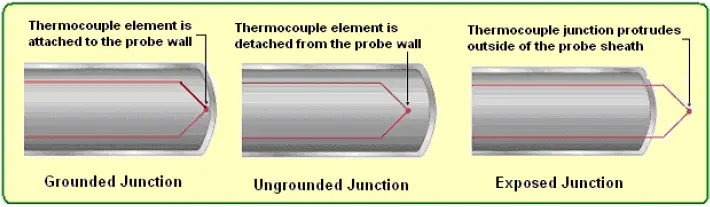
Sheathed thermocouple probes are available with one of three junction types: grounded, ungrounded or exposed.
Grounded Junction- In this type, the thermocouple wires are physically attached to the inside of the probe wall. This results in good heat transfer from the outside, through the probe wall to the thermocouple junction. The grounded junction is recommended for the measurement of static or flowing corrosive gas and liquid temperatures and for high pressure applications. The junction of a grounded thermocouple is welded to the protective sheath giving faster response than the ungrounded junction type.
Ungrounded Junction- In an underground probe, the thermocouple junction is detached from the probe wall. Response time is slowed down from the grounded style, but the ungrounded offers electrical isolation of 1.5 M1/2 at 500 Vdc in all diameters. An ungrounded junction is recommended for measurements in corrosive environments where it is desirable to have the thermocouple electronically isolated from and shielded by the sheath. The welded wire thermocouple is physically insulated from the thermocouple sheath by MgO powder (soft).
Exposed Junction- In the exposed junction style, the thermocouple protrudes out of the tip of the sheath and is exposed to the surrounding environment. This type offers the best response time, but is limited in use to non-corrosive and non-pressurized applications. The junction extends beyond the protective metallic sheath to give accurate fast response. The sheath insulation is sealed where the junction extends to prevent penetration of moisture or gas which could cause errors.
In summary, the exposed junction provides the quickest response time followed by grounded junction. Temperature measurement decisions can make or break the expected results of the process. Choosing the correct sensor for the application might be a difficult task, but processing that measured signal is also very critical.
Thermocouple Laws
First some notation:
Let T1 be the temperature of bath 1, and T2 be the temperature of bath 2.
Let V1-R be defined as the voltage produced by a thermocouple at temperature T1 when a proper reference junction at temperature TR is used (T R = reference temperature = 0 oC). V1-R is the voltage listed in the thermocouple tables at temperature T1.
Let V1-2 be defined as the difference in voltage between V1-R and V2-R,
V1-2 = V1-R – V2-R
Sign convention:
Negative sign errors can be problematic when working with these equations, if one is not consistent.
By convention, the thermocouple tables are constructed such that higher temperature yields higher thermo-junctive voltage.
In other words, it is always be assumed that the two thermocouple wires (let’s call them wire A and wire B) are connected to the voltmeter in such a way that the voltage is positive when the temperature being measured is greater than the reference temperature. Likewise, the voltage is negative when the temperature being measured is less than the reference temperature.
Since the standard reference temperature for thermocouple tables is 0ºC, positive temperatures in units of ºC yield positive thermo-junctive voltages, and negative temperatures in units of oC yield negative thermo-junctive voltages.
Note that if the wires are connected the opposite way to the voltmeter, the voltages will of course be of opposite sign.
There are three laws or rules that apply to thermocouples:
- Law of intermediate metals
“A third (intermediate) metal wire can be inserted in series with one of the wires without changing the voltage reading (provided that the two new junctions are at the same temperature)”.
Consider the setup below, where a rectangle around a thermo-junction indicates a constant temperature bath (e.g. a pot of boiling water or an ice-water bath).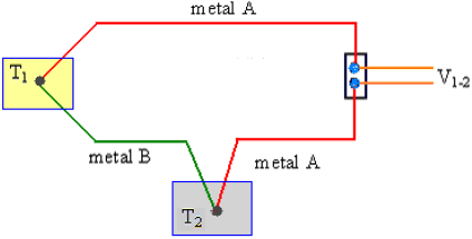
The law of intermediate metals states that the voltage reading, V1-2 does not change if one adds a third (intermediate) wire in line with any of the wires in the circuit, as sketched below: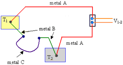
In the above diagram, it is assumed that both of the new junctions (between metal B and metal C) are at the same temperature, i.e. ambient temperature, Ta.
One can easily see that the law of intermediate metals must hold here, since whatever voltage is generated at one of the new junctions is exactly canceled by an equal and opposite voltage generated at the other new junction.
Likewise, metal C can be inserted anywhere else in the circuit without any effect on the output voltage, provided that the two new junctions are at the same temperature. For example, consider the following modified circuit:
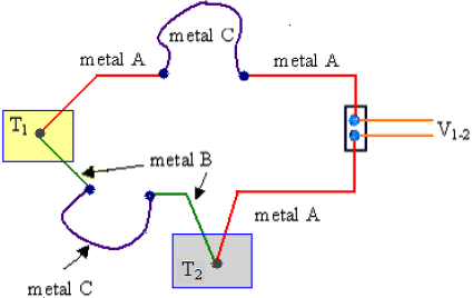
Again, if the two new junctions (this time between metals A and C) are at the same temperature, there is no net effect on the output voltage.
- Law of intermediate temperatures
“If identical thermocouples measure the temperature difference between T1 and T2, and the temperature difference between T2 and T3, then the sum of the corresponding voltages V1-2 + V2-3 must equal the voltage V1-3 generated by an identical thermocouple measuring the temperature difference between T1 and T3”.
Mathematical statement of the law of intermediate temperatures:
V1-3 = V1-2 + V2-3 for any three temperatures, T1, T2, and T3.
Consider the setup below, where six thermo-junctions are shown, two in each constant temperature bath. Note: To avoid clutter in the diagram, the copper leads of the DVM are no longer shown. Also, for brevity, letters A and B indicate metal A and metal B, two different types of thermocouple wires.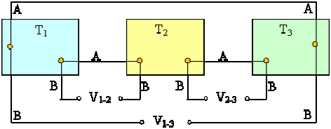
By the notation convention adopted here,
V1-3 = V1-R – V3-R,
which can be written as
V1-3 = (V1-R – V2-R) + (V2-R – V3-R)
But since (also by definition)
V1-2 = V1-R – V2-R, and
V2-3 = V2-R – V3-R,
it follows directly that
V1-3 = V1-2 + V2-3.
- Law of additive voltages
“For a given set of 3 thermocouple wires, A, B, and C, all measuring the same temperature difference T1 – T2, the voltage measured by wires A and C must equal the sum of the voltage measured by wires A and B and the voltage measured by wires B and C”.
Consider the setup below, where six thermo-junctions are shown, three in constant temperature bath T1, and three in constant temperature bath T2. As above, letters A, B, and C indicate different types of thermocouple wires.
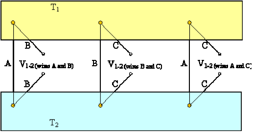
The law of additive voltages can be stated mathematically as:
V1-2 (wires A and C) = V1-2 (wires A and B) + V1-2 (wires B and C)
Or, rearranging in terms of voltage differences,
V1-2 (wires A and B) = V1-2 (wires A and C) – V1-2 (wires B and C).
Thermopile
A thermopile is defined as several thermocouples connected in series. For example, a thermopile with three sensing junctions is shown below:
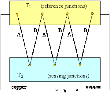
As T2 is increased, the output voltage increases significantly. The advantage of a thermopile (as compared to just one sensing junction) is increased sensitivity.
Here, the voltage output is three times that which is generated by just one thermocouple under otherwise identical conditions, as sketched below:
With enough sensing junctions, a thermopile can actually generate a useful voltage. For example, thermopiles are often used to control shut-off valves in furnaces.
Also Read: Basics of Thermocouple & RTD sensors
Thanks a lot for this vital informations…
but peltier efeect is for one single metal not for two dissimilar metals
The so called “modified circuit” does not work, because the two metal A wires are sensing two different temperatures, so will generate different EMF, so are not sensing the EMF generated on metal B on temperature difference at two ends. wikipedia gives a better explanation.