Inst ToolsInst ToolsInst Tools
  • Courses
  • Automation
    • PLC
    • Control System
    • Safety System
    • Communication
    • Fire & Gas System
  • Instrumentation
    • Design
    • Pressure
    • Temperature
    • Flow
    • Level
    • Vibration
    • Analyzer
    • Control Valve
    • Switch
    • Calibration
    • Erection & Commissioning
  • Interview
    • Instrumentation
    • Electrical
    • Electronics
    • Practical
  • Q&A
    • Instrumentation
    • Control System
    • Electrical
    • Electronics
    • Analog Electronics
    • Digital Electronics
    • Power Electronics
    • Microprocessor
  • Request
Search
  • Books
  • Software
  • Projects
  • Process
  • Tools
  • Basics
  • Formula
  • Power Plant
  • Root Cause Analysis
  • Electrical Basics
  • Animation
  • Standards
  • 4-20 mA Course
  • Siemens PLC Course
Reading: Why Are Neutral and Earth Separated?
Share
Font ResizerAa
Inst ToolsInst Tools
Font ResizerAa
  • Courses
  • Design
  • PLC
  • Interview
  • Control System
Search
  • Courses
  • Automation
    • PLC
    • Control System
    • Safety System
    • Communication
    • Fire & Gas System
  • Instrumentation
    • Design
    • Pressure
    • Temperature
    • Flow
    • Level
    • Vibration
    • Analyzer
    • Control Valve
    • Switch
    • Calibration
    • Erection & Commissioning
  • Interview
    • Instrumentation
    • Electrical
    • Electronics
    • Practical
  • Q&A
    • Instrumentation
    • Control System
    • Electrical
    • Electronics
    • Analog Electronics
    • Digital Electronics
    • Power Electronics
    • Microprocessor
  • Request
Follow US
All rights reserved. Reproduction in whole or in part without written permission is prohibited.
Inst Tools > Blog > Electrical Basics > Why Are Neutral and Earth Separated?

Why Are Neutral and Earth Separated?

In this article, we will learn why the neutral and earth wires are separated from each other in an electrical system.

Last updated: July 11, 2023 1:33 pm
Viral Nagda
Electrical Basics
No Comments
Share
6 Min Read
SHARE

Whenever we use electricity, we know about the wires used in it – phase, neutral, and earth. Actually, normal people do not care about what is going on in these wires and they just need electricity to use. But, the electrical engineers know the real fact about these wires. What separates them in their definition is also necessary to understand.

Contents
What is the difference between Neutral and Earth?Why do You have to Separate Earth and Neutral?

Mostly, we think that neutral and earth are the same types of connections; but it is not. There are differences between them and it is also to be noted that they are not connected with each other.

In this article, we will learn why the neutral and earth wires are separated from each other in an electrical system.

What is the difference between Neutral and Earth?

First of all, as discussed, we know that an electrical connection has three wires – line (phase), earth, and neutral. As per the basics of electricity, current flows from a positive terminal to the load and then back to the negative terminal.

Refer to the below image for understanding. A power supply has two terminals – positive and negative. The positive terminal is used to connect the line wire and the negative terminal is used to connect the neutral wire.

Why Are Neutral and Earth Separated

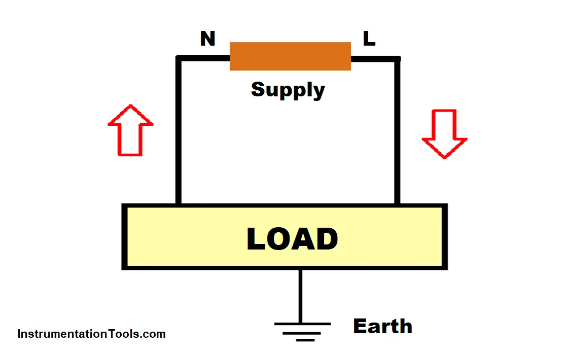
When the power supply is turned ON, the electricity flows through the phase wire to the load’s positive terminal. The return current is carried from the negative terminal of load to the negative terminal of the power supply, through the neutral wire.

The neutral wire is thus termed as the return current carrying path. As the current is consumed by the load, a very minimal current (almost equal to negligible) is present in the neutral wire.

Now, the load can be any metallic device. There are chances many times or most frequently that some current can lead to the metallic body of the device. If anyone accidentally touches the body, then he can get an electrical shock. If there is some means to nullify this leakage current, then this chance of shock can be eliminated. This is done by an earthing wire. The earth wire is connected to the body of the device, to the earth pit.

An earth pit is dug in some areas outside the electrical device’s presence. The earth wire goes from the body to this pit dug. Any leakage current is then carried from the ground wire to the ground point in the earth, as the earth has zero potential.

The grounding connection thus provides a safe path for the leakage current to flow outside and kill itself. It is to be noted that the leakage current can also be produced by external electromagnetic forces or surges acting on the body.

Why do You have to Separate Earth and Neutral?

Now that we have understood the difference between both these wires, let us see why they should not be bonded together. It must have been clear that the neutral wire is just required to complete the path and the ground wire is required to provide safety. Though both have minimal current, their purpose is different.

If any ground fault occurs, like ground leakage, it needs a path to carry this current to the ground pit. This is done by ground wire. If this wire is bonded with the neutral wire, then as the neutral wire too offers a low impedance path, the leakage current will flow in both wires. This will immediately damage the circuit. This is because, a circuit is designed to carry a certain rated amount of current, and any increase in current can trip the circuit.

The same thing can reverse happen with the ground wire. As the ground connection is just meant for safety purposes, the return current of the neutral wire will also flow to the ground wire; and can hamper the earth pit potential. This is extremely dangerous because if the earth is only having potential, then there will be no protection for any device connected to it. All the circuit breakers related to ground protection will trip frequently and electricity supply will be hampered to a great extent.

It is for these reasons that it is not required to connect both these wires together, even though they have very less current in them.

If you liked this article, then please subscribe to our YouTube Channel for Electrical, Electronics, Instrumentation, PLC, and SCADA video tutorials.

You can also follow us on Facebook and Twitter to receive daily updates.

Read Next:

  • What is SMPS? – Types
  • What is a Buchholz Relay?
  • VFD Installation Engineer Roles
  • Drives Application Handbook
  • Smart Grid Feeder Automation
Don't Miss Our Updates
Be the first to get exclusive content straight to your email.
We promise not to spam you. You can unsubscribe at any time.
Invalid email address
You've successfully subscribed !

Continue Reading

Electrical Terminology
Current Transformer Selection, Operation & Maintenance
Electrical Power Grid Automation
Electrical Drawings
Difference Between Permittivity and Permeability
MCB vs Fuse Questions and Answers
Share This Article
Facebook Whatsapp Whatsapp LinkedIn Copy Link
Share
Leave a Comment

Leave a Reply Cancel reply

Your email address will not be published. Required fields are marked *

Stay Connected

128.3kFollowersLike
69.1kFollowersFollow
210kSubscribersSubscribe
38kFollowersFollow

Categories

Explore More

Difference between Servo Motor and DC Motor
Difference Between Short Circuit and Ground Fault
Advantages of Star and Delta Systems
Circuit Breaker Making Capacity
What is Electrical Busbar? Types, Advantages, Disadvantages
Motor Control Center – Purpose, Classification, and Advantages
Lightning Arrester Basics and Terminology
Variable Motor Speed Control

Keep Learning

Motor Control On-Delay Timers Circuit

Motor Control Timer Circuit – Automatic Motor START and STOP

Difference Between Circuit Breaker and Disconnector

Difference Between Circuit Breaker and Disconnector

Electrical Terminal Blocks

How to Protect Electrical Terminal Blocks From Tampering?

Three phase induction motor nameplate

How to Size a Cable for Industrial AC Motors?

Intelligent Motor Control Center

What is an Intelligent Motor Control Center? – IMCC

Why is Motor Control Required in Control Systems

Why is Motor Control Required in Control Systems?

What is a Power Transformer

What is a Power Transformer? – Components and Types

Motor Maintenance

Motor Maintenance, Troubles, Regular Checks, Performance

Learn More

Economics of Power Generation Objective Questions

100+ Economics of Power Generation Objective Questions and Answers

Power Electronics Objective Questions

Single Phase Full Wave AC DC Converter MCQ

intouch Basics

How to Create Project in Wonderware Intouch?

Difference between Stepper Motor and Servo Motor

Valve stem travel

Control Valves Mechanical Friction Problems

Transistor Failure Rate Calculation

Transistor Failure Rate Calculation

Radar and Ultrasonic Level Transmitter Problems Troubleshooting

Radar and Ultrasonic Level Transmitter Practical Problems Troubleshooting

7 Investments for Single Mothers

7 Investments for Single Mothers

Menu

  • About
  • Privacy Policy
  • Copyright

Quick Links

  • Learn PLC
  • Helping Hand
  • Part Time Job

YouTube Subscribe

Follow US
All rights reserved. Reproduction in whole or in part without written permission is prohibited.
Welcome Back!

Sign in to your account

Username or Email Address
Password

Lost your password?