Inst ToolsInst ToolsInst Tools
  • Courses
  • Automation
    • PLC
    • Control System
    • Safety System
    • Communication
    • Fire & Gas System
  • Instrumentation
    • Design
    • Pressure
    • Temperature
    • Flow
    • Level
    • Vibration
    • Analyzer
    • Control Valve
    • Switch
    • Calibration
    • Erection & Commissioning
  • Interview
    • Instrumentation
    • Electrical
    • Electronics
    • Practical
  • Q&A
    • Instrumentation
    • Control System
    • Electrical
    • Electronics
    • Analog Electronics
    • Digital Electronics
    • Power Electronics
    • Microprocessor
  • Request
Search
  • Books
  • Software
  • Projects
  • Process
  • Tools
  • Basics
  • Formula
  • Power Plant
  • Root Cause Analysis
  • Electrical Basics
  • Animation
  • Standards
  • 4-20 mA Course
  • Siemens PLC Course
Reading: Working Principle of Overload Relay
Share
Notification Show More
Font ResizerAa
Inst ToolsInst Tools
Font ResizerAa
  • Courses
  • Design
  • PLC
  • Interview
  • Control System
Search
  • Courses
  • Automation
    • PLC
    • Control System
    • Safety System
    • Communication
    • Fire & Gas System
  • Instrumentation
    • Design
    • Pressure
    • Temperature
    • Flow
    • Level
    • Vibration
    • Analyzer
    • Control Valve
    • Switch
    • Calibration
    • Erection & Commissioning
  • Interview
    • Instrumentation
    • Electrical
    • Electronics
    • Practical
  • Q&A
    • Instrumentation
    • Control System
    • Electrical
    • Electronics
    • Analog Electronics
    • Digital Electronics
    • Power Electronics
    • Microprocessor
  • Request
Follow US
All rights reserved. Reproduction in whole or in part without written permission is prohibited.
Inst Tools > Blog > Electrical Basics > Working Principle of Overload Relay

Working Principle of Overload Relay

In this post, we will learn the working principle of overload relay, types, and applications.

Last updated: October 17, 2023 1:55 pm
Viral Nagda
Electrical Basics
No Comments
Share
4 Min Read
SHARE

In this post, we will learn the working principle of overload relay, types, and applications.

Contents
Overload RelayTypes of Overload RelaysBimetallic Thermal Overload RelayElectronic Overload RelayApplications of Overload Relays

Motor overload is defined as a condition where the motor draws excessive load current and heats it up. This condition can damage the motor windings.

To protect it from damage, an overload relay is used in series with its contactor; to protect the motor from overload and over-current. It is used in almost every motor starter.

The function of the overload relay is to continuously sense the load current and tripping the power supply to the motor. Thus, the motor is protected from overload and over current.

Overload Relay
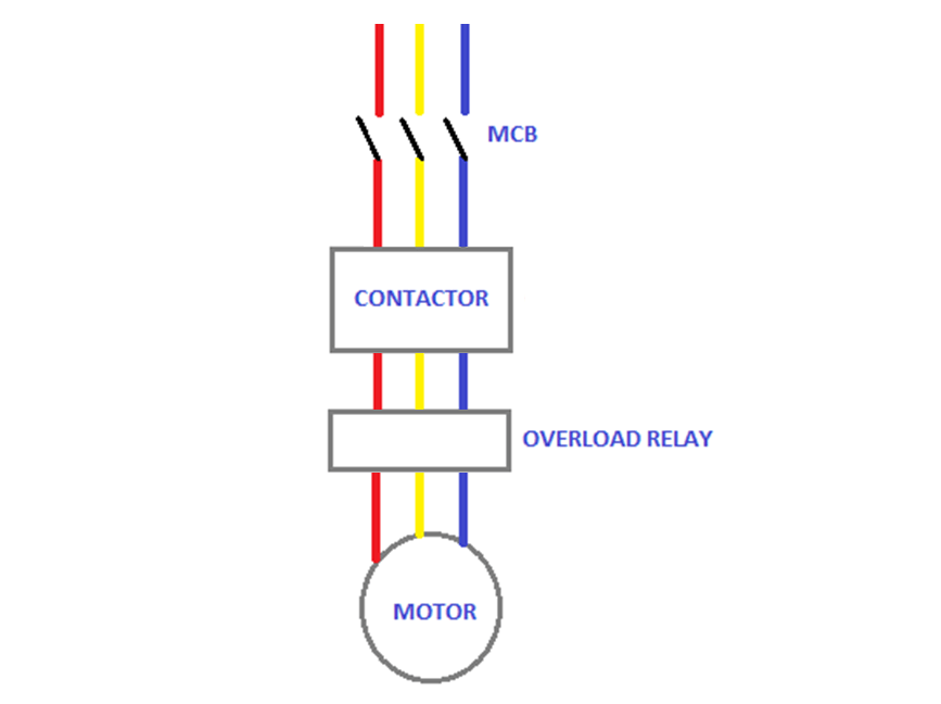
Working Principle of Overload Relay

Refer to the below image for its general connection. The three-phase supply from raw incoming power is fed to a contactor through MCB; and then to the motor through an overload relay.

The overload relay continuously monitors the load current drawn and cuts off the power supply when it exceeds a certain high limit.

Usually, the relay has the following terminals – L1, L2, L3 (for incoming power); T1, T2, T3 (for outgoing power), auxiliary contact for providing feedback to any control circuit; ampere range knob setting in the relay; trip reset button and a test button to test the control wiring.

Basically, this relay works in the principle of thermal heating. As current increases, the temperature of phase windings in the motor and wire too increases.

This temperature is sensed to determine the overload condition and when the temperature exceeds a predefined high set value, it trips the circuit.

Types of Overload Relays

Owing to this working, there are two types of overload relay –

  1. bimetallic thermal overload relay and
  2. electronic overload relay.

Bimetallic Thermal Overload Relay

In the bimetallic relay, a bimetallic strip is used and is placed in the circuit in such a way that the current flows through it.

The strip gets heated continuously due to its properties. When the current exceeds the limit, it gets heated in such a large way that it breaks the contact with the outgoing supply from it.

This is the traditional working of an overload relay. An overload relay was founded on the basis of this working principle.

Electronic Overload Relay

In an electronic relay, temperature sensors and current transformers are in the motor circuit to sense the rise in temperature and current.

PTC sensors are used to sense temperature. Due to use of microprocessors and sensors, the sensing technology of this type of relay is much accurate than a traditional bimetallic relay.

Also, the heat losses inside the relay are much lesser in this type than a bimetallic relay.

Applications of Overload Relays

Overload relays are extensively used in control circuits of motors; as they provide an auxiliary contact to the PLC.

This helps in additional protection of the overall circuit. You just have to set the tripping current in the relay according to your needs and also select the relay based on trip class.

Trip class is nothing but a trip check timer. It varies depending on various classes and considers the corresponding check timer to trip the circuit when it has sensed overload condition.

If you liked this article, then please subscribe to our YouTube Channel for Instrumentation, Electrical, PLC, and SCADA video tutorials.

You can also follow us on Facebook and Twitter to receive daily updates.

Read Next:

  • Motor Controller
  • Motor Protection Circuit
  • Bimetallic Thermometer
  • Contactor and its Principle
  • Spiral Bimetallic Thermometer
Don't Miss Our Updates
Be the first to get exclusive content straight to your email.
We promise not to spam you. You can unsubscribe at any time.
Invalid email address
You've successfully subscribed !

Continue Reading

What is Arc Protective Clothing? – Importance, Features, Materials
Motor Maintenance, Troubles, Regular Checks, Performance
Difference Between Circuit Breaker and Disconnector
What is a Time Delay Fuse? – Principles and Advantages
Worldwide Voltage & Frequency Values
Difference Between AA and AAA Batteries
Share This Article
Facebook Whatsapp Whatsapp LinkedIn Copy Link
Share
Leave a Comment

Leave a Reply Cancel reply

Your email address will not be published. Required fields are marked *

Stay Connected

128.3kFollowersLike
69.1kFollowersFollow
210kSubscribersSubscribe
38kFollowersFollow

Categories

Explore More

Electric Motors Noises – Types, Possible Sources, Reasons
Bus Riser in Switchgear
Automatic Motor Forward and Reverse Control using Timer
How Do Electrical Shorts and Ground Faults Trip Circuit Breakers?
Download Electrical Enclosure Book
How to Read and Understand an Electrical Single Line Diagram?
How to Test a Motor using Megger?
What is Vacuum Circuit Breaker?

Keep Learning

Electrical Frequency

One Nation One Grid One Frequency – Electrical Engineering

Types of Circuit Breakers

Types of Circuit Breakers, Advantages, Disadvantages

Why CT Secondary Should Never Be Kept Open?

Why CT Secondary Should Never Be Kept Open?

Bonding and Grounding Electrical Systems

Testing and Inspection of Bonding and Grounding Systems

Why is HV Testing important in Electrical Panels?

Why is HV Testing important in Electrical Panels?

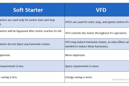
Difference between Soft Starter and VFD

Difference between Soft Starter and VFD

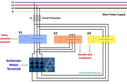
Dahlander Motor Control Circuit

Dahlander Motor Control Circuit and Power Circuit

Humming Sound in Transformer

Why is the Humming Sound Produced in Transformer?

Learn More

PLC Timer Programming Examples on Coffee Machine

PLC Timer Practice Exercise: Coffee Machine Programming

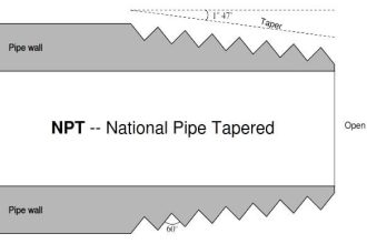
National Pipe Thread Cross Sectional View

What is Tapered Thread Pipe Fittings ?

Plant Air Storage Tank

Plant Air Storage Tank Pressure Fluctuations Root Cause Analysis

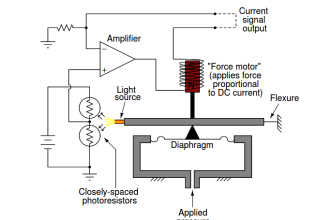
Pressure instruments example circuit

Motion-Balance and Force-Balance Instruments

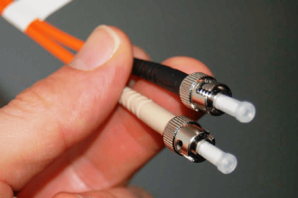
optical fibers terminations

Fiber Optic Data Communication

photo-diode

Photodiode Working Principle

Underground Cable Fault Identification Methods

Emergency Stop Push button

Emergency Stop Switch Spurious Trip

Menu

  • About
  • Privacy Policy
  • Copyright

Quick Links

  • Learn PLC
  • Helping Hand
  • Part Time Job

YouTube Subscribe

Follow US
All rights reserved. Reproduction in whole or in part without written permission is prohibited.
Welcome Back!

Sign in to your account

Username or Email Address
Password

Lost your password?