Inst ToolsInst ToolsInst Tools
  • Courses
  • Automation
    • PLC
    • Control System
    • Safety System
    • Communication
    • Fire & Gas System
  • Instrumentation
    • Design
    • Pressure
    • Temperature
    • Flow
    • Level
    • Vibration
    • Analyzer
    • Control Valve
    • Switch
    • Calibration
    • Erection & Commissioning
  • Interview
    • Instrumentation
    • Electrical
    • Electronics
    • Practical
  • Q&A
    • Instrumentation
    • Control System
    • Electrical
    • Electronics
    • Analog Electronics
    • Digital Electronics
    • Power Electronics
    • Microprocessor
  • Request
Search
  • Books
  • Software
  • Projects
  • Process
  • Tools
  • Basics
  • Formula
  • Power Plant
  • Root Cause Analysis
  • Electrical Basics
  • Animation
  • Standards
  • 4-20 mA Course
  • Siemens PLC Course
Reading: Why 4-20 mA Standard is so popular ?
Share
Font ResizerAa
Inst ToolsInst Tools
Font ResizerAa
  • Courses
  • Design
  • PLC
  • Interview
  • Control System
Search
  • Courses
  • Automation
    • PLC
    • Control System
    • Safety System
    • Communication
    • Fire & Gas System
  • Instrumentation
    • Design
    • Pressure
    • Temperature
    • Flow
    • Level
    • Vibration
    • Analyzer
    • Control Valve
    • Switch
    • Calibration
    • Erection & Commissioning
  • Interview
    • Instrumentation
    • Electrical
    • Electronics
    • Practical
  • Q&A
    • Instrumentation
    • Control System
    • Electrical
    • Electronics
    • Analog Electronics
    • Digital Electronics
    • Power Electronics
    • Microprocessor
  • Request
Follow US
All rights reserved. Reproduction in whole or in part without written permission is prohibited.
Inst Tools > Blog > Instrumentation Design > Why 4-20 mA Standard is so popular ?

Why 4-20 mA Standard is so popular ?

Last updated: August 29, 2019 4:42 pm
Editorial Staff
Instrumentation Design
No Comments
Share
4 Min Read
SHARE

4-20 mA Standard

4-20mA has an inherent ‘live zero’. Zero engineering units is 4.0mA, not 0.0mA. 0.0mA indicates an open circuit, a failure or a fault mode like cut wires or a dead transmitter. 0.0mA is not a valid reading of zero engineering units and a wake-up call that there’s something seriously wrong in the loop. (electrical current level below about 3.6mA is absolutely necessary because it is used to drive the electronics of loop powered devices).

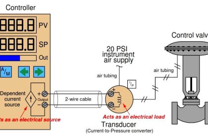
Any electrical circuit needs two conductors. In 4-20 mA’s ‘two-wire, loop powered’ form, a field transmitter gets its power over the same two wires as the signal, without a third or fourth wire for power.   This is a major plus when large numbers of field instruments or long wire runs are involved.

4-20 mA can be designed for Intrinsically Safe approval for use in hazardous areas, which allows troubleshooting the circuit while it’s ‘live’ and powered.

4-20 mA can carry HART® digital data superimposed on its primary DC signal, without sacrificing any of the properties above and without interfering with non-HART enabled analog inputs.

The 4-to-20 span and offset (with live zero at 20% of the span from zero) has the same 1:5 ratio as the widely used 3-15 psi pneumatic control signal.

Values slightly above and below the nominal 4-20mA can be and are used to signal a major fault.  (See the NAMUR NE43 standard.)

A 4-20 mA current signal is less susceptible to noise pickup than a voltage circuit, so 4-20 mA is relatively free from interference and cross-talk from other signals.

4-20 mA has little, if any, signal loss in its circuit; current regulation compensates for minor resistances in terminal boxes, whereas voltage drop across resistances for voltage signals creates an error.

4-20 mA works at relatively long distances (>1km at a nominal 24 VDC). Boosting the power supply voltage will drive the signal even farther.

Two-wire 4-20mA commercial instruments are isolated and floating so ground loops and their associated errors and faults are relatively rare.

4-20 mA is generally tolerant of copper cable length and type.

The response of 4-20mA is adequate for the vast majority of process sensing needs.

The original published standard for 4-20 mA, ISA SP50, was published in 1966, almost 50 years ago, generating widespread acceptance and creating an installed base of millions of points.

Electricians find it easy to wire and troubleshoot 4-20 mA. Its working principles are easily understood DC electronics.

When used with a nominal 24 VDC loop power supply, no one who touches the wire terminals gets shocked or even feels a tingle.

A cheap, $10 digital multimeter meter can be used to troubleshoot a 4-20 mA loop circuit.

4-20 mA can easily be measured in multiple ways:

With a milliameter inserted into the circuit or across a diode in the circuit

With a voltmeter as a voltage drop across a dropping resistor

With a Fluke 77x clamp meter

4-20 mA offers a wide choice of resistor values when converting to a IR voltage drop across the receiver input. Lots of resistor values, from 1 ohm to 500 ohms, have been used (250 ohms is the most common).

In summary, 4-20mA is simple and rugged.   It works well.

Share & leave us some comments on what you think about this topic or if you like to add something.

Also Read: Why Current Loop as Standard ?

Don't Miss Our Updates
Be the first to get exclusive content straight to your email.
We promise not to spam you. You can unsubscribe at any time.
Invalid email address
You've successfully subscribed !

Continue Reading

Control Valve Recommended Practices for Harsh Process Conditions
Selection Criteria of pH Analyzers
Basics of Permissive and Interlock Circuits
Basic Calculations of Instrument Air
Top 10 Facts about HART Technology
Role of an Instrumentation Design Engineer for Beginners
Share This Article
Facebook Whatsapp Whatsapp LinkedIn Copy Link
Share
Leave a Comment

Leave a Reply Cancel reply

Your email address will not be published. Required fields are marked *

Stay Connected

128.3kFollowersLike
69.1kFollowersFollow
210kSubscribersSubscribe
38kFollowersFollow

Categories

Explore More

Transmitter Detailed Specifications
Explain Operation of the Lamp Circuit ?
Instrument Numbering Philosophy
Motor Control Circuit Wiring
Level Transmitter and Level Gauge Design Tips
Interactions With Process Control Systems Philosophy
I&C Engineer Roles & Responsibilities – Instrumentation Design
Control Valve Packing

Keep Learning

NACE Standards - MR0103 Vs MR0175

NACE Standards – MR0103 Vs MR0175

Instrument Junction Box Specification

Instrument Junction Box Specification

Electromechanical_Relays Circuit

Relay Loop Back Circuit

Level Sensor Pressure vessel mounting

Level Instruments Design Rules

Insulation of Thermowell

Facts on Thermowell Insulation Thickness

how-to-select-a-fuse

How to Select a Fuse ?

Selecting the Best Inductive or Capacitive Sensor

Selecting the Best Inductive or Capacitive Sensor

Turbine Flow Meter

All About Turbine Meters

Learn More

Left-Hand Rule for Generators

DC Generator Theory

Basic Electronics Questions and Answers

Basic Electronics Questions and Answers

MCCB (Molded Case Circuit Breaker)

Industrial Circuit Breakers – Most Common Types – Principle

How transformer works?

How transformer works?

Laser Diode Working Principle

Laser Diode Working Principle

PLC ON DELAY TIMER FUNCTION

#6 PLC Best Practices – Validate Timers and Counters

Swirl Flowmeters Principle

Swirl Flow Meters Working Principle

Studio 5000 Tutorial PLC Programming for Digital Alarms

Studio 5000 Tutorial: PLC Programming for Digital Alarms

Menu

  • About
  • Privacy Policy
  • Copyright

Quick Links

  • Learn PLC
  • Helping Hand
  • Part Time Job

YouTube Subscribe

Follow US
All rights reserved. Reproduction in whole or in part without written permission is prohibited.
Welcome Back!

Sign in to your account

Username or Email Address
Password

Lost your password?