Inst ToolsInst ToolsInst Tools
  • Courses
  • Automation
    • PLC
    • Control System
    • Safety System
    • Communication
    • Fire & Gas System
  • Instrumentation
    • Design
    • Pressure
    • Temperature
    • Flow
    • Level
    • Vibration
    • Analyzer
    • Control Valve
    • Switch
    • Calibration
    • Erection & Commissioning
  • Interview
    • Instrumentation
    • Electrical
    • Electronics
    • Practical
  • Q&A
    • Instrumentation
    • Control System
    • Electrical
    • Electronics
    • Analog Electronics
    • Digital Electronics
    • Power Electronics
    • Microprocessor
  • Request
Search
  • Books
  • Software
  • Projects
  • Process
  • Tools
  • Basics
  • Formula
  • Power Plant
  • Root Cause Analysis
  • Electrical Basics
  • Animation
  • Standards
  • 4-20 mA Course
  • Siemens PLC Course
Reading: Phototransistor Circuit Example
Share
Notification Show More
Font ResizerAa
Inst ToolsInst Tools
Font ResizerAa
  • Courses
  • Design
  • PLC
  • Interview
  • Control System
Search
  • Courses
  • Automation
    • PLC
    • Control System
    • Safety System
    • Communication
    • Fire & Gas System
  • Instrumentation
    • Design
    • Pressure
    • Temperature
    • Flow
    • Level
    • Vibration
    • Analyzer
    • Control Valve
    • Switch
    • Calibration
    • Erection & Commissioning
  • Interview
    • Instrumentation
    • Electrical
    • Electronics
    • Practical
  • Q&A
    • Instrumentation
    • Control System
    • Electrical
    • Electronics
    • Analog Electronics
    • Digital Electronics
    • Power Electronics
    • Microprocessor
  • Request
Follow US
All rights reserved. Reproduction in whole or in part without written permission is prohibited.
Inst Tools > Blog > Electronic Devices & Circuits > Phototransistor Circuit Example

Phototransistor Circuit Example

Last updated: September 27, 2016 7:52 am
Editorial Staff
Electronic Devices & Circuits
No Comments
Share
1 Min Read
SHARE

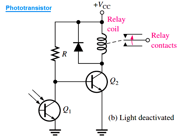
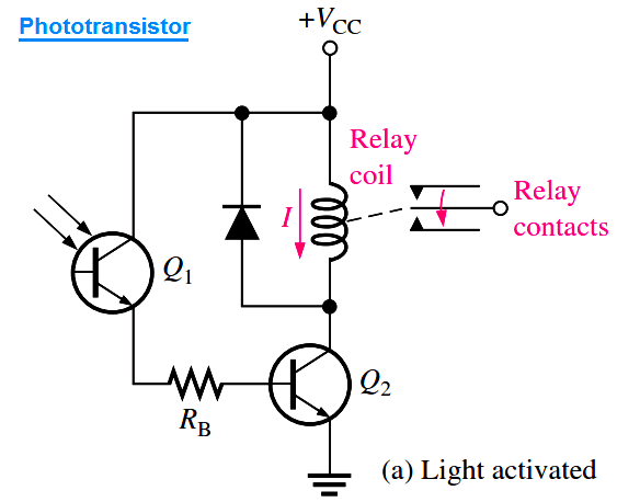
Phototransistors are used in a variety of applications. A light-operated relay circuit is shown in below Figure (a). The phototransistor Q1 drives the BJT Q2. When there is sufficient incident light on Q1, transistor Q2 is driven into saturation, and collector current through the relay coil energizes the relay. The diode across the relay coil prevents, by its limiting action, a large voltage transient from occurring at the collector of Q2 when the transistor turns off.

phototransistor-circuit

The below Figure (b) shows a circuit in which a relay is deactivated by incident light on the phototransistor. When there is insufficient light, transistor Q2 is biased on, keeping the relay energized. When there is sufficient light, phototransistor Q1 turns on; this pulls the base of Q2 low, thus turning Q2 off and de-energizing the relay.

phototransistor-circuit-example

Don't Miss Our Updates
Be the first to get exclusive content straight to your email.
We promise not to spam you. You can unsubscribe at any time.
Invalid email address
You've successfully subscribed !

Continue Reading

Transistor Collector Characteristic Curves
Transistors Questions & Answers
Testing a Transistor with a Digital Multimeter
Power MOSFET Safe Operating Area
Why Silicon is preferred over Germanium ?
Transistor as a Switch Working Principle
Share This Article
Facebook Whatsapp Whatsapp LinkedIn Copy Link
Share
Leave a Comment

Leave a Reply Cancel reply

Your email address will not be published. Required fields are marked *

Stay Connected

128.3kFollowersLike
69.1kFollowersFollow
210kSubscribersSubscribe
38kFollowersFollow

Categories

Explore More

Operation of Zener Diode Voltage Regulator
JFET Working Animation
Seven Segment Display Working Principle
Transistor as an Amplifier in Common Emitter
Amplifiers Questions & Answers
Schottky Diode Working Principle
Diodes Voltage Quadrupler
Freewheeling Diode Working Principle

Keep Learning

Transistor Stabilisation

Transistor Stabilisation

Dependent Voltage Source

Dependent Voltage Source

photo-diode

Photodiode Working Principle

Classification of Bridge Circuits

Classification of Bridge Circuits

Ideal Diode Characteristics

Ideal Diode Characteristics

Electron Gun of CRT

Electron Gun of Cathode Ray Tube

Transistor Voltage Divider Bias

Transistor Voltage Divider Bias

Tunnel Diode

Tunnel Diode Working Principle

Learn More

Lift check valves

What is Lift Check Valve ?

Differential Pressure Gauge Principle

Differential Pressure Gauge Principle

Control Loops Multiple Choice Questions

Control Loop Multiple Choice Questions

Thermocouple Extension Lead Minimizer Circuit

Thermocouple Wires and Extension Lead Issues

Using Kirchhoff’s Voltage Law to find Current with one Source

Applying Kirchhoff’s Voltage Law

Pressure gauges with capsule elements

Pressure Gauges with Capsule Sensor Principle

If Else Statement in SCL Language

If Else Statement in SCL Language

Electrical Machines Objective Questions

Electrical Machines MCQ Series 7

Menu

  • About
  • Privacy Policy
  • Copyright

Quick Links

  • Learn PLC
  • Helping Hand
  • Part Time Job

YouTube Subscribe

Follow US
All rights reserved. Reproduction in whole or in part without written permission is prohibited.
Welcome Back!

Sign in to your account

Username or Email Address
Password

Lost your password?