Inst ToolsInst ToolsInst Tools
  • Ask
  • Courses
  • Videos
  • Q & A
    • Interview
      • Instrumentation
      • Electronics
      • Electrical
      • Practical Questions
    • MCQ
      • Instrumentation MCQ
      • Electrical MCQ
      • Electronics MCQ
      • Control Systems MCQ
      • Analog Electronics MCQ
      • Digital Electronics MCQ
      • Power Electronics MCQ
      • Microprocessor MCQ
      • Multiple Choice Questions
  • EE
    • Electronics
      • Electronics Q & A
      • Electronic Basics
      • Electronic Devices & Circuits
      • Electronics Animation
      • Digital Electronics
    • Electrical
      • Electrical Basics
      • Electrical Q & A
      • Power Electronics
      • Electrical Machines
      • Electrical Animation
      • Power Systems
      • Switchgear & Protection
      • Transmission & Distribution
  • Measure
    • Control Valves
    • Calibration
    • Temperature
    • Pressure
    • Flow
    • Level
    • Analyzers
    • Switches
    • Vibration
    • Solenoid Valve
  • Control
    • PLC Tutorials
    • Control Systems
    • Safety Instrumented System (SIS)
    • Communication
    • Fire & Gas System
  • More
    • Design
    • Tools
    • Animation
    • Basics
    • Formulas
    • Standards
    • TextBooks
    • Common
    • Software
    • Excel Tools
    • Erection & Commissioning
    • Process Fundamentals
    • Videos
    • Books
Search
All rights reserved. Reproduction in whole or in part without written permission is prohibited.
Reading: DP Transmitter Error Calculations
Share
Notification Show More
Font ResizerAa
Inst ToolsInst Tools
Font ResizerAa
  • Courses
  • PLC Tutorials
  • Control Systems
Search
  • Ask
  • Courses
  • Videos
  • Q & A
    • Interview
    • MCQ
  • EE
    • Electronics
    • Electrical
  • Measure
    • Control Valves
    • Calibration
    • Temperature
    • Pressure
    • Flow
    • Level
    • Analyzers
    • Switches
    • Vibration
    • Solenoid Valve
  • Control
    • PLC Tutorials
    • Control Systems
    • Safety Instrumented System (SIS)
    • Communication
    • Fire & Gas System
  • More
    • Design
    • Tools
    • Animation
    • Basics
    • Formulas
    • Standards
    • TextBooks
    • Common
    • Software
    • Excel Tools
    • Erection & Commissioning
    • Process Fundamentals
    • Videos
    • Books
Follow US
All rights reserved. Reproduction in whole or in part without written permission is prohibited.
Inst Tools > Blog > Practical Questions > DP Transmitter Error Calculations

DP Transmitter Error Calculations

Last updated: June 6, 2018 9:51 am
Editorial Staff
Practical Questions
No Comments
Share
2 Min Read
SHARE

A “smart” DP transmitter with built-in square root characterization is used to measure flow through a pipe.

The orifice plate range is 0 to 125 inches WC at 0 to 277 gallons per minute:

Smart DP transmitter Formula

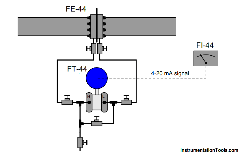
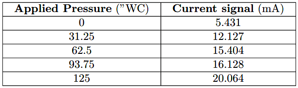
A technician removes the transmitter from service and tests it by applying several air pressures to the “H” port while leaving the “L” port vented. Here are the As-Found results:

DP transmitter Readings

Calculate the largest error, in percent of (output signal) span.

Also, determine whether this looks like a zero or span error, and whether that error exists in the input (ADC) of the smart transmitter or in the output (DAC).

Answer :

This is a zero error in the input (ADC) of the smart transmitter, the greatest error being at the 0% point (5.431 mA instead of 4.00 mA = +8.94%).

As you can see, the square-root function inside the transmitter exaggerates the sensor calibration error at the low end of the scale.

This same zero-shift error of +1 inch WC is hardly noticeable at the high end (20.006 mA instead of 20.000 mA = +0.4% error).

More DP Transmitter Questions

Flow Transmitter Readings mismatch with DCS
DP Transmitter Calibration Errors
Smart DP Transmitter Flow Meter Calculations
Pitot Tube Flowmeter Calculations


Don't Miss Our Updates
Be the first to get exclusive content straight to your email.
We promise not to spam you. You can unsubscribe at any time.
Invalid email address
You've successfully subscribed !
Signal Strength of Guided-wave Radar Level Instrument
Calculate Hydraulic System Fluid Pressure
Solenoid Valves Questions & Answers – 2
Calculate the Transmitter Values
Troubleshoot Allen Bradley PLC Logic
Share This Article
Facebook Whatsapp Whatsapp LinkedIn Copy Link
Share
Leave a Comment

Leave a Reply Cancel reply

Your email address will not be published. Required fields are marked *

Stay Connected

128.3kFollowersLike
69.1kFollowersFollow
208kSubscribersSubscribe
38kFollowersFollow

Categories

Recent Comments

  • Guifty Shimica on Top Non-PLC Certification Courses for Automation Professionals
  • Guifty Shimica on Top Non-PLC Certification Courses for Automation Professionals
  • MIHARITSOA Aina Sitraka on Top Non-PLC Certification Courses for Automation Professionals
  • Vaishnavi on Free Instrumentation Course for Trainee Engineers

Related Articles

Remote Seal Pressure Transmitter Temperature

Importance of Temperature in Remote Seal Pressure Transmitter

Fisher model 546 I to P transducer

Fisher model 546 I/P transducer

Allen-Bradley MicroLogix controller

Programmable Logic Controller (PLC) Questions and Answers – 15

Allen-Bradley MicroLogix 1000 controller

PLC Switch Actuation Status

Pressure Gauge with Block and Bleed Valves

Pressure Gauge with Block and Bleed Valves

Electric-driven Air Compressor Troubleshooting

Electric-driven Air Compressor Troubleshooting

Identify the Pressure Gauge Error

Identify the Pressure Gauge Error

Inductive proximity switches

How to Connect Proximity Switch (Source Type) to Make LED ON ?

More Articles

Digital Control Systems Multiple Choice Questions

Digital Control Systems Multiple Choice Questions

Nuisance Alarms

What is Alarm Shelving? – Nuisance Alarms, Types, Suppression

AI AO DI DO Signals

What are AI, AO, DI, and DO? – Definition, Examples, Purpose

Industrial motor control using PLC instruction list programming

PLC Instruction List for Motor Reverse and Forward Direction

Calculate Power in Parallel RC Circuit

Calculate Power in Parallel RC Circuit

4-20mA Transmitter NAMUR Signal Levels

4-20mA Transmitter NAMUR Signal Levels

Diode-positive-limiter

Positive & Negative Diode Clippers

Omron PLC Online Training Course

Omron PLC Online Training Course

Follow US
All rights reserved. Reproduction in whole or in part without written permission is prohibited.
Welcome Back!

Sign in to your account

Username or Email Address
Password

Lost your password?