Inst ToolsInst ToolsInst Tools
  • Courses
  • Automation
    • PLC
    • Control System
    • Safety System
    • Communication
    • Fire & Gas System
  • Instrumentation
    • Design
    • Pressure
    • Temperature
    • Flow
    • Level
    • Vibration
    • Analyzer
    • Control Valve
    • Switch
    • Calibration
    • Erection & Commissioning
  • Interview
    • Instrumentation
    • Electrical
    • Electronics
    • Practical
  • Q&A
    • Instrumentation
    • Control System
    • Electrical
    • Electronics
    • Analog Electronics
    • Digital Electronics
    • Power Electronics
    • Microprocessor
  • Request
Search
  • Books
  • Software
  • Projects
  • Process
  • Tools
  • Basics
  • Formula
  • Power Plant
  • Root Cause Analysis
  • Electrical Basics
  • Animation
  • Standards
  • 4-20 mA Course
  • Siemens PLC Course
Reading: What LIC and FIC Controllers will do?
Share
Notification Show More
Font ResizerAa
Inst ToolsInst Tools
Font ResizerAa
  • Courses
  • Design
  • PLC
  • Interview
  • Control System
Search
  • Courses
  • Automation
    • PLC
    • Control System
    • Safety System
    • Communication
    • Fire & Gas System
  • Instrumentation
    • Design
    • Pressure
    • Temperature
    • Flow
    • Level
    • Vibration
    • Analyzer
    • Control Valve
    • Switch
    • Calibration
    • Erection & Commissioning
  • Interview
    • Instrumentation
    • Electrical
    • Electronics
    • Practical
  • Q&A
    • Instrumentation
    • Control System
    • Electrical
    • Electronics
    • Analog Electronics
    • Digital Electronics
    • Power Electronics
    • Microprocessor
  • Request
Follow US
All rights reserved. Reproduction in whole or in part without written permission is prohibited.
Inst Tools > Blog > Control Systems > What LIC and FIC Controllers will do?

What LIC and FIC Controllers will do?

Last updated: August 13, 2020 8:48 pm
Editorial Staff
Control Systems
No Comments
Share
2 Min Read
SHARE

In this example problem, we discuss about both LIC and FIC controllers and what will they do over time if the flow or level transmitter fails or if control valve not working in the loop.

Contents
What LIC and FIC Controllers will do?Question 1:Question 2:Answer 1:Answer 2:

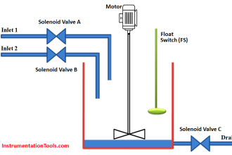
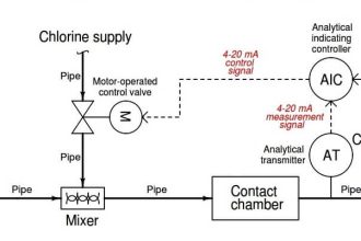
This clearwell water level control system for a drinking water treatment facility maintains a constant level of water following filtration, for sourcing to customers:

What LIC and FIC Controllers will do?

LIC and FIC Controllers

Question 1:

Determine what both controllers (LIC and FIC) will do over time if the flow transmitter fails in such a way that it registers zero flow regardless of the actual flow rate of water through it.

Assume the level transmitter is direct-acting (i.e. greater signal with greater water level) and that the control valve is signal- to-open (fail closed).

Question 2:

Determine what both controllers (LIC and FIC) will do over time if the control valve fails in such a way that it ignores the controller’s output and opens wide.

Assume both transmitters are direct-acting (i.e. greater signal with greater flow ; greater signal with greater water level) and that the control valve is signal-to-open (fail closed).

Answer 1:

The flow controller (FIC) will send a “full-open” signal to the valve, because its transmitter indicates the flow rate is less than it should be.

The level controller’s output will saturate low, telling the flow controller to stop the flow as the clearwell level rises well above setpoint due to the uncontrolled flow coming in.

Answer 2:

The flow controller (FIC) will send a “close” signal to the valve, because its transmitter indicates the flow rate is excessive.

The level controller’s output will saturate low, telling the flow controller to stop the flow as the clearwell level rises well above setpoint due to the uncontrolled flow coming in.

Join the Discussion! Share your answers with us through below comments section.

Read Next:

  • Single Loop Controller
  • Over-Tuned PID Controller
  • Loop Tuning Tips
  • Types of Interlocks
  • Liquid Level Control
Don't Miss Our Updates
Be the first to get exclusive content straight to your email.
We promise not to spam you. You can unsubscribe at any time.
Invalid email address
You've successfully subscribed !

Continue Reading

Yokogawa DCS and SIS System Architecture
Overview of Split Range Control
Types of Interlocks
Troubleshooting Pump Control Circuit
Functional Design Specifications for DCS and SIS Projects – FDS Document
What is Instrument Hook Up Diagram ?
Share This Article
Facebook Whatsapp Whatsapp LinkedIn Copy Link
Share
Leave a Comment

Leave a Reply Cancel reply

Your email address will not be published. Required fields are marked *

Stay Connected

128.3kFollowersLike
69.1kFollowersFollow
210kSubscribersSubscribe
38kFollowersFollow

Categories

Explore More

Troubleshooting a 4-20mA Current loop
What is Override Control? – Need & Applications
What are Static UPS and Rotary UPS?
Process Control Instrumentation
Difference between Fieldbus, Profibus and HART Protocols
Boiler Drum Level Control Systems
What is Electromagnetic Noise Interference?
ESD System Insights: Signals for Emergency Valve Shutdown Explained

Keep Learning

how-to-avoid-bad-grounds

How to Avoid Bad Grounds ?

How Valve Positioners act as Cascade Control Systems in a Loop?

How Valve Positioners act as Cascade Control Systems in a Loop?

Relay Internal Parts

Relay Operation, Types, Symbols & Characteristics

Unmanaged Switch

Managed Switch vs Unmanaged Switch

AI AO DI DO Signals

What are AI, AO, DI, and DO? – Definition, Examples, Purpose

Control Sytem Open Loop and Closed Loop

Introduction to Control System

Relation Control

Relation Control System

Control System Vendor Internal Test Procedures

Vendor View of Supplying Industrial Process Control & Safety Systems

Learn More

Single Bearing Motor Stator Winding

Critical High KiloWatt Motor Winding Burnout Threats

Pressure Gauge Datasheet

How to Fill up Instrument Datasheet? – Pressure Gauge Specifications & Standards

dissolved-oxygen-probe-calibration-procedure

Dissolved oxygen probe calibration procedure

Quiz on Sensor Transducer

Quiz on Sensor Transducer

Gas Detectors Bump Testing

What is Bump Testing ?

Step by step guide for Gas Flow Meter Calibration

Step by Step Guide for Gas Flow Meter Calibration

magnetic-flow-meter-earthing

Importance of Magnetic Flow Meters Grounding

Rotary Lobe Air Compressor

Centrifugal Compressors

Menu

  • About
  • Privacy Policy
  • Copyright

Quick Links

  • Learn PLC
  • Helping Hand
  • Part Time Job

YouTube Subscribe

Follow US
All rights reserved. Reproduction in whole or in part without written permission is prohibited.
Welcome Back!

Sign in to your account

Username or Email Address
Password

Lost your password?