The hydraulic valve is a fluid-operated device, used to direct its output as desired in a variety of applications.
Hydraulic valves are classified according to physical construction, type of actuation, number of ways-positions, etc.
Following are the main categories of Hydraulic valves and they are of three types.
- Hydraulic Pressure Control Valves
- Hydraulic Direction Control Valves
- Hydraulic Flow Control Valves
Hydraulic Pressure Control Valves
A hydraulic power transmission system employs pressurized flow to convey the energy to perform desired work. Therefore, pressure control of the working fluids is one of the foremost basic control functions in hydraulic system power transmission.
Different types of pressure control valves are designed to perform a wide variety of functions from keeping systems operate safely below a maximum allowable pressure limit to allowing only certain pressure fluids into a specific branch in a circuit.
Variety of sub-functions are performed by pressure control valves like
- Pressure relief,
- Pressure reducing,
- Pressure sequencing,
- Counter Balancing,
- Unloading valves.
Almost all pressure control valves are normally closed (NC) valves, except the pressure reducing valves, which are normally open (NO) in general.
All pressure control valves are operated using the balance between pressure forces and the loaded spring forces on the poppet or spool.
This is to control the orifice opening to achieve the pressure control objective by means of controlling the pressure drop across the valve.
Pressure Relief Valve
The relief valve keeps the system pressure below a desired upper limit to maintain a set pressure in part of a hydraulic circuit.
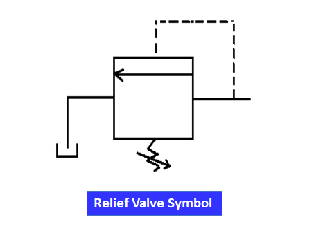
Protects the hydraulic system from over-pressure and directs part of it to drain.
The relief valve avoids the over-pressurization of the hydraulic system.
Pressure Reducing Valve
Pressure reducing valve is normally an open valve, when the pressure in the valve outlet increases above the set pressure, push the pilot downwards and close its flow path.
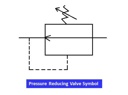
The purpose of pressure reducing valve is to limit the pressure downstream of the valve in order to control the maximum pressure a part of the system undergoes.
Sequence Valve
The sequence valves are employed in some machines that have to work in a specific sequence to perform the work, Sequence valves are introduced in the circuit.
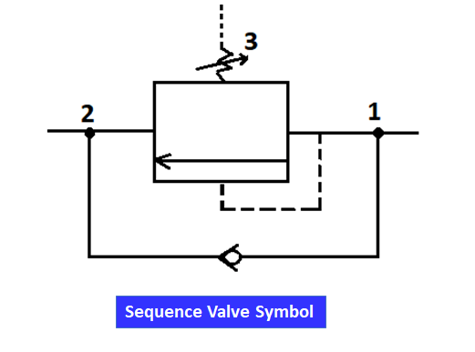
In the case of a machine that has several hydraulic actuators, it is used to assure priority hydraulic pressure in one system before another can operate.
Sequence valves are employed in parallel circuits. Multiple actuators are often controlled in a sequential fashion as desired.
Counter-balance Valve
The counter-balance valves are utilized in open center position directional control valves and vertical cylinders either to hold in place without risk of drifting.
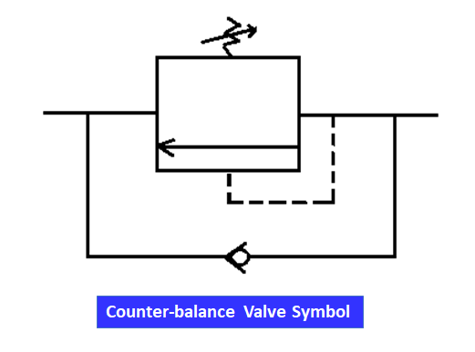
Also precisely control the descent while lowering the load. Uncontrolled fast movement of the piston in a cylinder can be avoided.
It offers certain back pressure or resistance of the hydraulic fluid to avoid fast cylinder strokes.
Counterbalance valves are placed closely to hydraulic actuators or directly on the actuator.
Unloading Valve
In certain cases, instead of relieving the pressure over a relief valve, completely unload the pump flow to the tank by incorporating an unloading valve in the system.
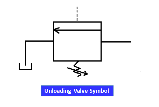
The best application is that the Hydraulic system utilizes two pumps, one with the high pressure-low flow and low pressure-high flow pumps.
Hydraulic Direction Control Valves
Directional control valves provide links between various parts of the hydraulic system by connecting, disconnecting, and changing oil flow direction.
In the hydraulic system, directional control valves include
- Check valves,
- Shuttle valves and
- Multi-port, multi-position directional control valves.
Check Valve
Check valves are used to limit back flowing in fluid systems. This is like an electrical diode since it permits flow in only one direction.
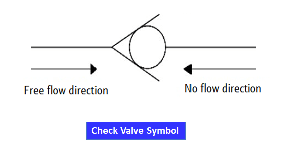
There is also a pressure drop analogous to voltage drop with the flow of current through a diode.
Shuttle Valve
In a particular application, the supply of fluid to a subsystem must be from more than one source to meet system demand. In these cases we can use a shuttle valve.
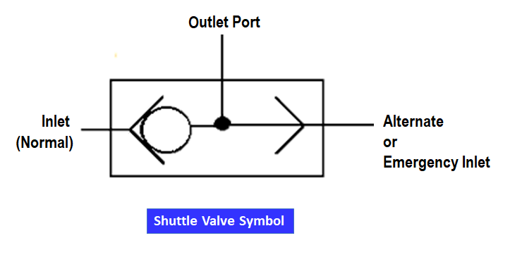
An emergency system is provided as another source of pressure. It is slightly at low pressure than normal inlet pressure and opens in the event of normal system failure.
Multi-port Multi-position Valves
Directional control valves are described by the number of port connections and switching positions.
For example, 2/2- way valve is described with the first letter by a two-port and the second letter by two switching positions. 3/2, 4/2, 4/3, 5/2 way valves are few to mention.
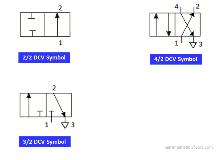
The directional control valves are actuated by manual, electrical, mechanical, hydraulic, and pneumatic force.
A two-way valve is a simple on-off valve used to control fluid supply through the pressure port and the working port of the valve.
A three-way valve control fluid through the pressure port, working port, and exhaust port of the valve.
Hydraulic Flow Control Valves
The basic purpose of flow control valves is to regulate the quantity of the fluid flow supplied to the branch circuit to control the actuator speed.
They are so many types, three basic flow control valves are discussed in this article.
- Non-compensation flow control valve
- Pressure-compensated flow control valve
- Flow-dividing control valve
Non Compensation Flow Control Valves
With the pressure drop between upstream and downstream of the valve, the flow rate passing through the valve will change.
The most simple and practical method of non-compensation flow control is probably the use of orifices, which is also the most basic pressure control device.
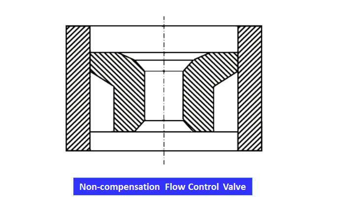
A simple orifice can be directly placed in the path of a fluid flow transfer line.
Such an orifice creates a pressure drop to increase the resistance in the line, which will force more flow to move into the other parallel branches to achieve the goal of flow control in the particular line.
Pressure Compensated Flow Control Valves
Needle valves are designed so as to finely control the orifice area by turning the needle to regulate the opening of the valve.
Needle valves are often used as meter-in or meter-out flow control in so many hydraulic control systems.
Needle-type flow control valves are generally used only on low-power systems or for flow rate-control applications.
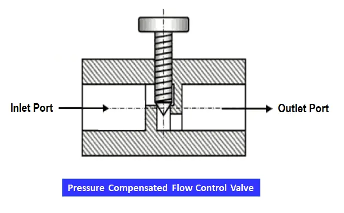
In certain applications, a branch circuit often requests a uniform flow supply regardless of the variations in either the system pressure or load pressure.
The non-compensated flow-control valves will be unable to satisfy such performance requirements, in those cases, a pressure-compensated flow control valve is desirable.
Flow-dividing Control Valves
Flow-dividing control valves often called flow dividers.
Flow dividers are designed in such a way that they split-flow supplied from one pump equally or proportionally to two output circuits that may be operating at different pressures.
Flows supplied to each circuit are generally pre-planned by the design of the valve.
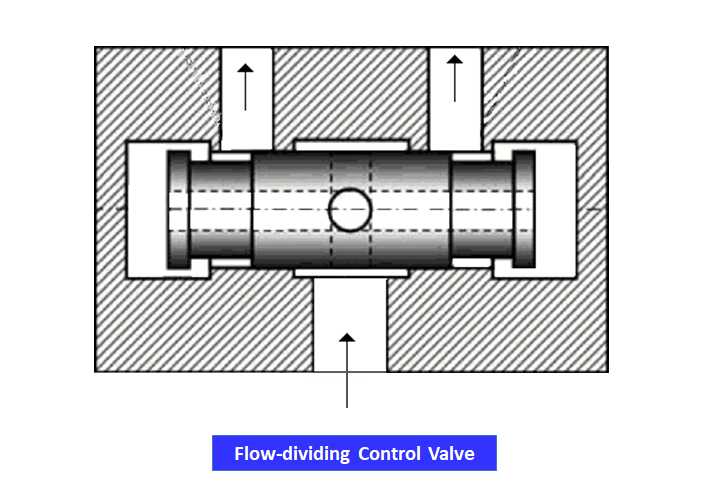
The flow from the pump port (P) is split into two streams in the path and supplied to fluid compartments at both ends of the spool.
The fluid is then passed to the actuators in both circuits via the left-hand side and right-hand side flow-passing orifices.
Reference: Fundamentals of mobile heavy equipment by Own C Duffy, Gus Write, Scott A. Heard.
If you liked this article, then please subscribe to our YouTube Channel for Instrumentation, Electrical, PLC, and SCADA video tutorials.
You can also follow us on Facebook and Twitter to receive daily updates.
Read Next:
- Valve Commissioning
- What is a Pilot Valve?
- What is a Poppet Valve?
- Valve Flow Direction
- Solenoid Manual Reset

