Inst ToolsInst ToolsInst Tools
  • Ask
  • Courses
  • Videos
  • Q & A
    • Interview
      • Instrumentation
      • Electronics
      • Electrical
      • Practical Questions
    • MCQ
      • Instrumentation MCQ
      • Electrical MCQ
      • Electronics MCQ
      • Control Systems MCQ
      • Analog Electronics MCQ
      • Digital Electronics MCQ
      • Power Electronics MCQ
      • Microprocessor MCQ
      • Multiple Choice Questions
  • EE
    • Electronics
      • Electronics Q & A
      • Electronic Basics
      • Electronic Devices & Circuits
      • Electronics Animation
      • Digital Electronics
    • Electrical
      • Electrical Basics
      • Electrical Q & A
      • Power Electronics
      • Electrical Machines
      • Electrical Animation
      • Power Systems
      • Switchgear & Protection
      • Transmission & Distribution
  • Measure
    • Control Valves
    • Calibration
    • Temperature
    • Pressure
    • Flow
    • Level
    • Analyzers
    • Switches
    • Vibration
    • Solenoid Valve
  • Control
    • PLC Tutorials
    • Control Systems
    • Safety Instrumented System (SIS)
    • Communication
    • Fire & Gas System
  • More
    • Design
    • Tools
    • Animation
    • Basics
    • Formulas
    • Standards
    • TextBooks
    • Common
    • Software
    • Excel Tools
    • Erection & Commissioning
    • Process Fundamentals
    • Videos
    • Books
Search
All rights reserved. Reproduction in whole or in part without written permission is prohibited.
Reading: Transformer Voltage Ratio
Share
Notification Show More
Font ResizerAa
Inst ToolsInst Tools
Font ResizerAa
  • Courses
  • PLC Tutorials
  • Control Systems
Search
  • Ask
  • Courses
  • Videos
  • Q & A
    • Interview
    • MCQ
  • EE
    • Electronics
    • Electrical
  • Measure
    • Control Valves
    • Calibration
    • Temperature
    • Pressure
    • Flow
    • Level
    • Analyzers
    • Switches
    • Vibration
    • Solenoid Valve
  • Control
    • PLC Tutorials
    • Control Systems
    • Safety Instrumented System (SIS)
    • Communication
    • Fire & Gas System
  • More
    • Design
    • Tools
    • Animation
    • Basics
    • Formulas
    • Standards
    • TextBooks
    • Common
    • Software
    • Excel Tools
    • Erection & Commissioning
    • Process Fundamentals
    • Videos
    • Books
Follow US
All rights reserved. Reproduction in whole or in part without written permission is prohibited.
Inst Tools > Blog > Electrical Theory > Transformer Voltage Ratio

Transformer Voltage Ratio

Last updated: August 6, 2018 11:10 pm
Editorial Staff
Electrical Theory
No Comments
Share
3 Min Read
SHARE

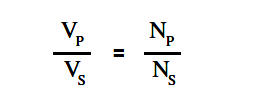
The voltage of the windings in a transformer is directly proportional to the number of turns on the coils. This relationship is expressed in below Equation.

Transformer Voltage Ratio

where

VP = voltage on primary coil

VS = voltage on secondary coil

NP = number of turns on the primary coil

NS = number of turns on the secondary coil

The ratio of primary voltage to secondary voltage is known as the voltage ratio (VR). As mentioned previously, the ratio of primary turns of wire to secondary turns of wire is known as the turns ratio (TR). By substituting into the above Equation, we find that the voltage ratio is equal to the turns ratio.

VR  =  TR

A voltage ratio of 1:5 means that for each volt on the primary, there will be 5 volts on the secondary. If the secondary voltage of a transformer is greater than the primary voltage, the transformer is referred to as a “step-up” transformer. A ratio of 5:1 means that for every 5 volts on the primary, there will only be 1 volt on the secondary. When secondary voltage is less than primary voltage, the transformer is referred to as a “step-down” transformer.

Example 1:

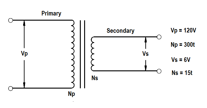
A transformer reduces voltage from 120 volts in the primary to 6 volts in the secondary. If the primary winding has 300 turns and the secondary has 15 turns, find the voltage and turns ratio.

Transformer voltage and turns ratio

Solution:

VR = Vp/Vs

VR = 120/60

VR =  20 : 1

TR = Np/Ns

TR = 300/15

TR =  20 : 1

Example 2:

An iron core transformer with a primary voltage of 240 volts has 250 turns in the primary and 50 turns in the secondary. Find the secondary voltage.

Solution:

Transformer Voltage Ratio

Solve for Vs

Vs  = (Ns/Np) Vp

Vs  = (50/250) 240

Vs  = 48 volts

Example 3:

A power transformer has a turns ratio of 1:4. If the secondary coil has 5000 turns and secondary voltage is 60 volts, find the voltage ratio, VP , and NP.

Solution:

VR = TR

VR = 1 : 4

VP / VS = VR = 1 : 4 = 1/4

VP = (1/4) VS

VP = 60/4

VP = 15 volts

TR = NP / NS

TR = 1 / 4

NP = (1/4) NS

NP = 5000/4

NP = 1250 turns

Don't Miss Our Updates
Be the first to get exclusive content straight to your email.
We promise not to spam you. You can unsubscribe at any time.
Invalid email address
You've successfully subscribed !
Impedance in RL Circuits
AC Generator Theory
What is a circuit breaker ?
Ampere Hour Meter
Voltage and Current Phase Relationships in an Inductive Circuit
Share This Article
Facebook Whatsapp Whatsapp LinkedIn Copy Link
Share
Leave a Comment

Leave a Reply Cancel reply

Your email address will not be published. Required fields are marked *

Stay Connected

128.3kFollowersLike
69.1kFollowersFollow
208kSubscribersSubscribe
38kFollowersFollow

Categories

Recent Comments

  • Guifty Shimica on Top Non-PLC Certification Courses for Automation Professionals
  • Guifty Shimica on Top Non-PLC Certification Courses for Automation Professionals
  • MIHARITSOA Aina Sitraka on Top Non-PLC Certification Courses for Automation Professionals
  • Vaishnavi on Free Instrumentation Course for Trainee Engineers

Related Articles

Simple RC Circuit

Impedance in RC Circuits

Types of Fuses

Electrical System Components and Protection Devices

Electric Short Circuit

Electric Circuit : Open & Short Circuits

Megger Circuit Diagram

Multimeter & Megger Principle

Center Tap Full-Wave Rectifier

Full-Wave Rectifier Circuit

Inductor Principle

Inductance and Inductive Reactance

DC Motor Action

DC Motor Speed

3-Wire, Three-Phase Delta Wiring System

3-Wire, Three-Phase Delta Wiring System

More Articles

Draw a Ladder Logic to control a bulb using push buttons in PLC

Concept of Latching in PLC

Foundation Fieldbus Signal Conversion Formula

Foundation Fieldbus Signal Conversion Formula

Basic Electronics Questions and Answers

Basic Electronics Questions and Answers

Gas Analyzers Interview Questions

Gas Analyzers Interview Questions and Answers

PLC Program for Conveyor Motor

PLC Conveyor Motor Ladder Logic

Industrial Automation Architecture reference model

Industrial Automation System Architecture Reference Model

Difference between RCCB and RCBO

Difference between RCCB and RCBO

Transmitter Proof Testing

Transmitter Proof Testing

Follow US
All rights reserved. Reproduction in whole or in part without written permission is prohibited.
Welcome Back!

Sign in to your account

Username or Email Address
Password

Lost your password?