Inst ToolsInst ToolsInst Tools
  • Courses
  • Automation
    • PLC
    • Control System
    • Safety System
    • Communication
    • Fire & Gas System
  • Instrumentation
    • Design
    • Pressure
    • Temperature
    • Flow
    • Level
    • Vibration
    • Analyzer
    • Control Valve
    • Switch
    • Calibration
    • Erection & Commissioning
  • Interview
    • Instrumentation
    • Electrical
    • Electronics
    • Practical
  • Q&A
    • Instrumentation
    • Control System
    • Electrical
    • Electronics
    • Analog Electronics
    • Digital Electronics
    • Power Electronics
    • Microprocessor
  • Request
Search
  • Books
  • Software
  • Projects
  • Process
  • Tools
  • Basics
  • Formula
  • Power Plant
  • Root Cause Analysis
  • Electrical Basics
  • Animation
  • Standards
  • 4-20 mA Course
  • Siemens PLC Course
Reading: Three Phase Systems
Share
Font ResizerAa
Inst ToolsInst Tools
Font ResizerAa
  • Courses
  • Design
  • PLC
  • Interview
  • Control System
Search
  • Courses
  • Automation
    • PLC
    • Control System
    • Safety System
    • Communication
    • Fire & Gas System
  • Instrumentation
    • Design
    • Pressure
    • Temperature
    • Flow
    • Level
    • Vibration
    • Analyzer
    • Control Valve
    • Switch
    • Calibration
    • Erection & Commissioning
  • Interview
    • Instrumentation
    • Electrical
    • Electronics
    • Practical
  • Q&A
    • Instrumentation
    • Control System
    • Electrical
    • Electronics
    • Analog Electronics
    • Digital Electronics
    • Power Electronics
    • Microprocessor
  • Request
Follow US
All rights reserved. Reproduction in whole or in part without written permission is prohibited.
Inst Tools > Blog > Electrical Theory > Three Phase Systems

Three Phase Systems

Last updated: August 2, 2018 5:41 pm
Editorial Staff
Electrical Theory
No Comments
Share
1 Min Read
SHARE

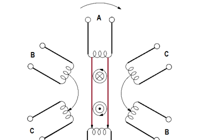
A three-phase (3φ) system is a combination of three single-phase systems. In a 3φ balanced system, power comes from a 3φ AC generator that produces three separate and equal voltages, each of which is 120° out of phase with the other voltages (Figure 10).

Three-Phase AC

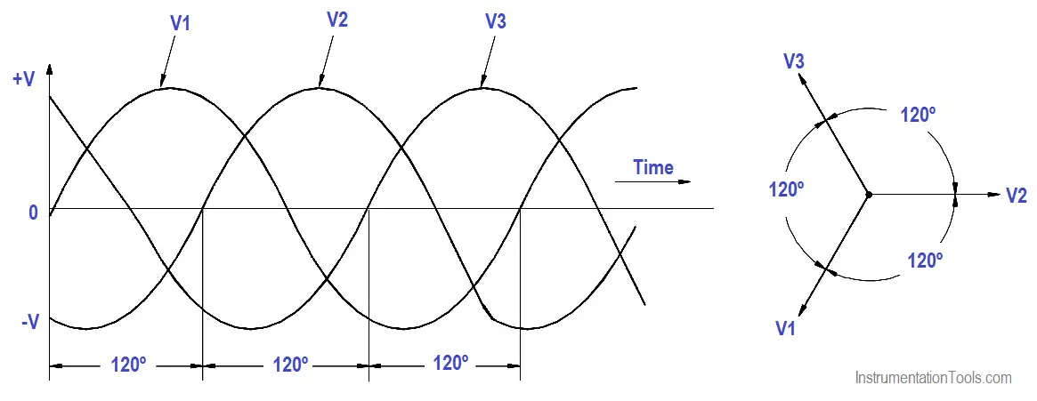
Figure 10 : Three-Phase AC

Three-phase equipment (motors, transformers, etc.) weighs less than single-phase equipment of the same power rating. They have a wide range of voltages and can be used for single-phase loads. Three-phase equipment is smaller in size, weighs less, and is more efficient than single-phase equipment.

Three-phase systems can be connected in two different ways. If the three common ends of each phase are connected at a common point and the other three ends are connected to a 3φ line, it is called a wye, or Y, connection (Figure 11). If the three phases are connected in series to form a closed loop, it is called a delta, or ∆, connection.

3φ AC Power Connections

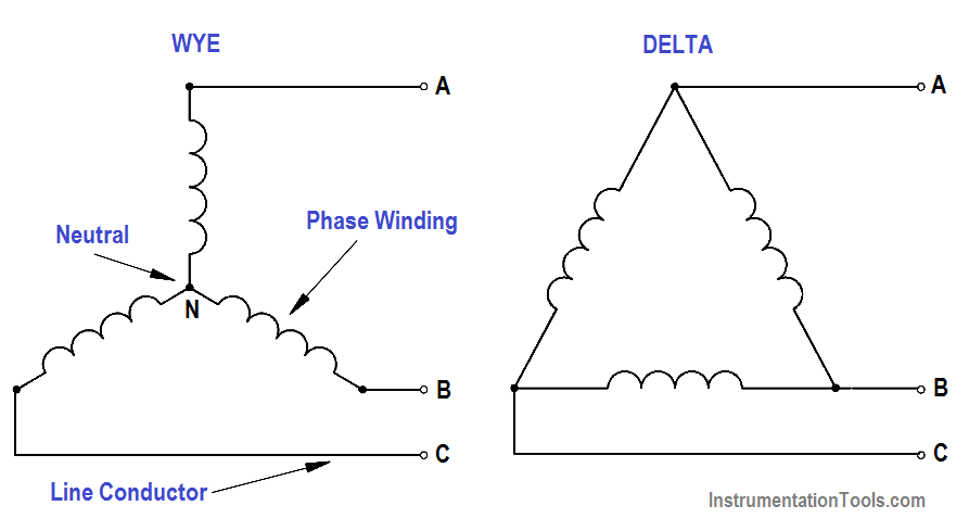
Figure 11 : 3φ AC Power Connections

Don't Miss Our Updates
Be the first to get exclusive content straight to your email.
We promise not to spam you. You can unsubscribe at any time.
Invalid email address
You've successfully subscribed !

Continue Reading

Induction Motor
Electro-Dynamo Meter Movement
Capacitor
Parallel Circuit
Starting a Synchronous Motor
Series and Parallel Inductors
Share This Article
Facebook Whatsapp Whatsapp LinkedIn Copy Link
Share
Leave a Comment

Leave a Reply Cancel reply

Your email address will not be published. Required fields are marked *

Stay Connected

128.3kFollowersLike
69.1kFollowersFollow
210kSubscribersSubscribe
38kFollowersFollow

Categories

Explore More

Parallel AC Generators
Batteries
Series and Parallel Capacitors
Parallel Short Circuit Faults
4-Wire, Three-Phase Wye Wiring System
DC Motor Theory
DC Circuit Analysis Loop Equations
What is Electricity ?

Keep Learning

Three Phase Transformer Connections

Three Phase Transformer Connections

Using Kirchhoff’s Voltage Law to find Current with one Source

Applying Kirchhoff’s Voltage Law

Parallel RLC Circuit

Resonance, Resonant Frequency, Series and Parallel Resonance

Transformer Coil Polarity

Transformer Coil Polarity

Types of Capacitors

Types of Capacitors

Ground Detector Lamp Method Principle

Ground Detector Principle

Calculate Power in Series RC Circuit

Calculate Power in Series RC Circuit

DC Motor Connections

DC Motor Connections

Learn More

Control Valve Cv Formula

Control Valve Cv calculation

Types of Inductors

What is an Inductor? – Types of Inductors

Remote Seals Transmitters Temperature Error

Remote Seal Transmitters Temperature Error

Hot wire Anemometer Principle

Hot Wire Anemometer Principle and Types

Digital Control Valve Working Principle

Digital Control Valve Working Principle

Cybersecurity in PLC

Cybersecurity in PLC

Closed Tank Liquid Level Measurement using Pressure Transmitter

Inferential Measurement based on Pressure

Roller Conveyor

Difference Between Belt Conveyor and Roller Conveyor

Menu

  • About
  • Privacy Policy
  • Copyright

Quick Links

  • Learn PLC
  • Helping Hand
  • Part Time Job

YouTube Subscribe

Follow US
All rights reserved. Reproduction in whole or in part without written permission is prohibited.
Welcome Back!

Sign in to your account

Username or Email Address
Password

Lost your password?