When you are developing a PLC program, you need to ensure that it is tested and validated properly before showing it to the customer. This is because a PLC program has many parts in it, like logic, configuration, settings, etc.
So, it is necessary to test and validate each and every part, regardless of which program will malfunction. If there are bugs in configuration or logic, then the system will malfunction at the site.
To avoid this, most programmers spend hours testing the PLC logic and it is a very important step done by them. In this post, we will learn the testing and validation process of PLC development.
Testing and Validation in PLC Development
Some of the points related to PLC testing and validation are mentioned below.
- Gather stakeholders for an initial meeting to discuss the scope, objectives, and requirements of the PLC project.
- Formulate the objectives and acceptance criteria for both testing and validation.
- Allocate resources, including team members, hardware, and software tools, required for the testing and validation process.
- Prepare detailed functional design specifications (FDS) that will serve as the foundation for PLC program development and testing.
- Develop the initial code blocks and routines based on the functional design specifications.
- Write test plans specifically for unit testing, identifying what each unit should accomplish and how to test it.
- Execute the unit tests, following the test plans and recording results for each function or routine.
- Create test plans for integration testing, outlining how different code blocks and routines will be combined and tested as a single entity.
- Perform integration testing, validating the whole program’s functionality and interoperability with other systems.
- Develop the FAT protocol, specifying the criteria that the system must meet to be considered acceptable.
- Conduct the FAT based on the FAT protocol in a simulated environment to ensure all requirements are met.
- Draft detailed validation protocols that define how validation will be carried out, what will be checked, and what constitutes acceptable results.
- Review the validation protocols and obtain approvals from quality assurance and other stakeholders.
- Implement the validation protocols, document results, and identify any deviations or failures.
- Create a SAT protocol, focusing on the real-world environment where the PLC system will operate.
- Conduct SAT to verify that the PLC system works reliably in its intended operating environment.
- Prepare comprehensive documentation of the testing and validation activities, results, and any corrective actions taken.
- Obtain final approval from all stakeholders, ensuring the PLC system is both tested and validated.
- Set up processes to monitor the PLC system’s performance and schedule regular re-testing and re-validation activities.
- Archive all PLC project documentation and code, and formally close out the project.
The above steps provide a simple guide for preparing testing and validation in a new PLC development project.
Let us have a look at some important steps one by one which need to be followed till the end for proper functioning.
IO Mapping
PLC functions according to inputs and outputs. So, the very first step in testing the program is checking IO mapping in PLC. You have to either force each digital input on the simulation or give actual hardware input to the PLC.
One by one, if the mapping is proper, then the same will be reflected in your graphics and program. This verifies digital inputs. Follow the same process for analog inputs. But, for analog inputs, you have to give multiple raw counts rather than just one count.
A wide range of counts gives you a proper idea of whether the channel is functioning properly or not. Then, for digital outputs, you have to force them one by one. If the PLC outputs are turning on and off according to the sequence, then your DO mapping is proper.
Follow the same process for analog outputs and give a wide range of raw counts instead of a single count. You will get a proper idea of whether the AO channel is functioning properly or not.
Communication Protocols Checking
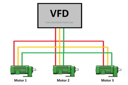
Once the IOs have been verified in the PLC program, the next step is to check communication and network addresses. Suppose a PLC has an Ethernet port and a Modbus RTU port. You have connected an HMI to the Ethernet port and three VFDs to the Modbus port. Modbus port is being used to transfer and receive data with VFD, like current, frequency, voltage, etc.
These mappings have been done by you in the PLC logic. You have to first check the Ethernet port by testing whether the IP is pinging or not; and whether it is communicating with HMI or not. Then, you have to establish Modbus communication and check whether the data is being communicated properly with PLC or not.
This clears your hardware part completely because you can now communicate data properly to the field; either through hard IO or soft IO. These two basic steps are the first step in your validation.
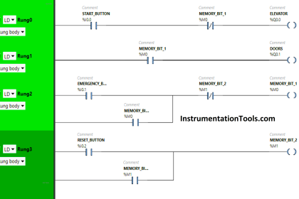
Manual Mode
Some systems have manual mode without critical interlocks and some systems have manual mode with critical interlocks. To check manual mode, you have to turn on each and every output step by step and check whether the actual physical output is turning on or not.
This first step verifies whether the physical DO or AO has been properly linked with manual mode buttons or not. Then, you have to generate corresponding alarms and check whether the output is turning off or not.
Only the linked outputs should turn off. The remaining outputs should not be impacted. This ensures that all the outputs have been linked properly in the program with proper interlocks. Because, once the manual mode has been cleared, it will be confirmed that the physical outputs can be turned on manually and auto mode can then be checked more easily.
Directly checking auto mode logic will confuse the programmer as to what output is getting on or off. Verifying manual mode will ensure that individual outputs are being turned on or not.
Auto Mode
The next big step is checking auto mode. The auto mode comes as a verifying sequence with interlocks. Every system is given a control logic document that shows how the sequence works with proper interlocks and output matrix.
The PLC programmer has to ensure that when any sequence is running, the corresponding outputs are turning on / off accordingly or not. Also, the sequence is running properly with interlocks or not?
Auto mode logic when made must be mostly divided into four parts
- Turning on the outputs,
- Writing the sequence flow,
- Linking interlocks and alarms, and
- Showing the current running status.
This technique makes the program flow very easy to look at and troubleshoot.
One should try to avoid the constant use of set–reset coils and ladder logic. Ladder logic is easy to use, but when run in simulation online, it consumes time to troubleshoot.
Also, set-reset coils are difficult to manage, because once a set coil is used, then care must be taken to reset it somewhere. Otherwise, the bit will remain set if the condition is not written properly.
In this way, we saw the testing and validation process in PLC development.
If you liked this article, then please subscribe to our YouTube Channel for Instrumentation, Electrical, PLC, and SCADA video tutorials.
You can also follow us on Facebook and Twitter to receive daily updates.
Read Next:
- UDT in PLC Programming
- PLC Fault Diagnosis Documents
- PID Controller Control System
- PLC, DCS, RTU, SCADA, and PAC
- Safety in PLC System Design