Inst ToolsInst ToolsInst Tools
  • Courses
  • Automation
    • PLC
    • Control System
    • Safety System
    • Communication
    • Fire & Gas System
  • Instrumentation
    • Design
    • Pressure
    • Temperature
    • Flow
    • Level
    • Vibration
    • Analyzer
    • Control Valve
    • Switch
    • Calibration
    • Erection & Commissioning
  • Interview
    • Instrumentation
    • Electrical
    • Electronics
    • Practical
  • Q&A
    • Instrumentation
    • Control System
    • Electrical
    • Electronics
    • Analog Electronics
    • Digital Electronics
    • Power Electronics
    • Microprocessor
  • Request
Search
  • Books
  • Software
  • Projects
  • Process
  • Tools
  • Basics
  • Formula
  • Power Plant
  • Root Cause Analysis
  • Electrical Basics
  • Animation
  • Standards
  • 4-20 mA Course
  • Siemens PLC Course
Reading: Stroke Checking Procedure for GCV, SRV, IGV, and LFBV
Share
Font ResizerAa
Inst ToolsInst Tools
Font ResizerAa
  • Courses
  • Design
  • PLC
  • Interview
  • Control System
Search
  • Courses
  • Automation
    • PLC
    • Control System
    • Safety System
    • Communication
    • Fire & Gas System
  • Instrumentation
    • Design
    • Pressure
    • Temperature
    • Flow
    • Level
    • Vibration
    • Analyzer
    • Control Valve
    • Switch
    • Calibration
    • Erection & Commissioning
  • Interview
    • Instrumentation
    • Electrical
    • Electronics
    • Practical
  • Q&A
    • Instrumentation
    • Control System
    • Electrical
    • Electronics
    • Analog Electronics
    • Digital Electronics
    • Power Electronics
    • Microprocessor
  • Request
Follow US
All rights reserved. Reproduction in whole or in part without written permission is prohibited.
Inst Tools > Blog > Calibration > Stroke Checking Procedure for GCV, SRV, IGV, and LFBV

Stroke Checking Procedure for GCV, SRV, IGV, and LFBV

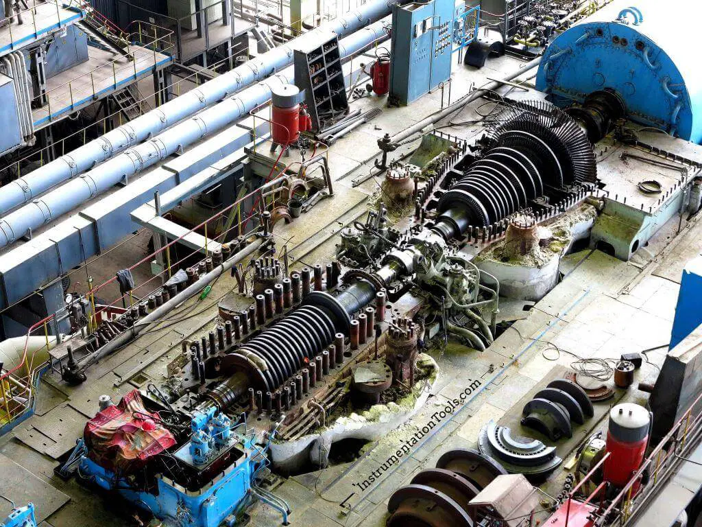
Learn the stroke checking procedure for GCV, SRV, IGV, and LFBV using the Mark V gas turbine control system.
Last updated: October 17, 2023 2:14 pm
Editorial Staff
Calibration Control Systems Power Plant
No Comments
Share
6 Min Read
SHARE

Learn the stroke checking procedure for GCV, SRV, IGV, and LFBV using the Mark V gas turbine control system.

Contents
GCV / SRV Stroke CheckingIGV Stroke CheckingLFBV Stroke Checking
Stroke Checking Procedure for GCV, SRV, IGV, and LFBV

Make sure that cool down, crank, or off mode is selected (L3ADJ should be 1).

Make sure that Equipment is isolated by the operation department and clearance is given for stroke checking.

Make sure that upstream pipeline gas is vented. L20FSX status should be “1”. Otherwise it can be forced to 1.

Make sure that ALOP and AHOP are running and hydraulic oil pressure is established.

Make sure that your selection of Unit1/Unit2 as per the Gas Turbine-1/2

Make sure that Mark-V Selection is in local.

Insert following signals required for forcing & monitoring the Turning gear speed, Hydraulic pressure, trip oil pressure etc

HQP – Hydraulic pressure  

TNH – Turning gear speed

GFOT – Trip oil pressure –Gas fuel

LFOT – Trip oil pressure – Liquid fuel

L20TV1X – Trip solenoid valve of IGV

L20FG1X – Trip Solenoid valve of GCV/SRV

L20FL1X – Trip Solenoid valve of Liq. fuel b/p valve

GCV / SRV Stroke Checking

Enable maintenance password

Go to logic forcing display

Force L4_XTP to 0 (If Turning gear is ON and required to be kept ON, as GT cool down is not over. In this case L4 not to be forced to 1)

If turning gear is off force L4 to 1

Caution: Don’t Force L4 to 1, it will affect machine Turning gear operation

Force the following two signals for stroking the GCV or SRV     

* Force L20TV1X to 1 (For energising Trip solenoid valve of IGV)

* Force L20FG1X to 1 (For energising Trip Solenoid valve of GCV/SRV)

If required vent the gas between shut of valve and SRV by forcing L20PSX to 1  

If required keep the shut of valve at filter skid close by forcing L20FSX to 0  

(Force 1 to open and 0 to close the valve)

Save points and quit Logic Forcing Display. After forcing above points, see gas fuel trip oil pressure GFOT is above 5 bar.

Mark-V Screen

Enable with password

Go to “Auto calibrate” page

Select “Gas Control Valve” or  “Stop/Speed Ratio valve”

Click on “ENABLE COMMAND” SOFT BUTTON

Click on “OK” Soft button

Click on “Enable Manual”

Enter Manual set point, Note down the % of opening and LVDT Voltage.

Select Value – Required value

Enable command & execute

Once the calibration is over, press IDLE ABORT and exit.

IGV Stroke Checking

Force L4_XTP to 0 (If Turning gear is ON and required to be kept ON, as GT cool down is not over. In this case L4 not to be forced to 1)

Caution: Don’t Force L4 to 1, it will affect machine Turning gear operation

If turning gear is off force L4 to 1

* Force L20TV1X to 1 and L20FG1X to 1 (For Energising Trip Solenoid valve of ICV)

Save points and quit Logic Forcing Display. After forcing above points, see gas fuel trip oil pressure GFOT is above 5 bar.

Mark-V Screen

Enable with password

Go to “Auto calibrate” page

Select “Inlet Guide vane control”

Click on “ENABLE COMMAND” SOFT BUTTON

Click on “OK” Soft button

Click on “Enable Manual”

Enter Manual set point, Note down the % of opening and LVDT Voltage.

Select Value – Required value

Enable command & execute

Once the calibration is over, press IDLE ABORT and exit.

LFBV Stroke Checking

Force L4_XTP to 0 (If Turning gear is ON and required to be kept ON, as GT cool down is not over. In this case L4 not to be forced to 1)

Caution: Don’t Force L4 to 1, it will affect machine Turning gear operation

If turning gear is off force L4 to 1

* Force L20FL1X to 1 (For Energising Trip Solenoid valve of Liq. fuel b/p valve)

Save points and quit Logic Forcing Display. After forcing above points, see gas fuel trip oil pressure LFOT is above 5 bar.

Mark-V Screen

Enable with password

Go to “Auto calibrate” page

Select “Liquid fuel bypass valve”

Click on “ENABLE COMMAND” SOFT BUTTON

Click on “OK” Soft button

Click on “Enable Manual”

Enter Manual set point, Note down the % of opening and LVDT Voltage.

Select Value – Required value

Enable command & execute

Once the calibration is over, press IDLE ABORT and exit.

Read Next:

  • DCS Commissioning Procedure
  • Gas Turbine Control System
  • Gas Turbine Interview Questions
  • Types of Turbine Protection
  • Forcing and Modifying PLC Logic
Don't Miss Our Updates
Be the first to get exclusive content straight to your email.
We promise not to spam you. You can unsubscribe at any time.
Invalid email address
You've successfully subscribed !

Continue Reading

How to Tune a Loop in DeltaV System
Troubleshooting a 4-20mA Current loop
Waste Water Control System
Overview of HIPPS System
Recognizing an Over-Tuned PID Controller by Phase Shift
Troubleshooting with Loop Calibrator
Share This Article
Facebook Whatsapp Whatsapp LinkedIn Copy Link
Share
Leave a Comment

Leave a Reply Cancel reply

Your email address will not be published. Required fields are marked *

Stay Connected

128.3kFollowersLike
69.1kFollowersFollow
210kSubscribersSubscribe
38kFollowersFollow

Categories

Explore More

Pressure Transmitter Calibration Procedure
De-energize to Safe Loop philosophy
What is PID Controller Bumpless Transfer ?
Single Element Drum Level Control System
Calibration Procedure of Voltmeter and Ammeter
Process Control Automation PLC Quiz
PLC Connection between Instrument, Junction Box, Marshalling & System Cabinet
Gas Turbine Troubleshooting Tips

Keep Learning

Why Calibration is Important

Why Calibration is Important?

Gas Detectors Calibration

Calibration of Gas Detectors

PID Controller Functions

PID Controller Functions

Types of Cables used in Industrial Automation

Types of Cables used in Industrial Automation

Workstation Healthiness Checks

Workstation Healthiness Checks

Yokogawa DCS Tutorials - Configuration of Analog Input (Transmitter)

Yokogawa DCS Tutorials – Configuration of Analog Input (Transmitter)

IACS Network

Remote Connectivity to Industrial Automation Systems

Power Supply Unit with Diode Protection

Why we use Diode Protection Modules ?

Learn More

Dahlander Motor Control Circuit

Dahlander Motor Control Circuit and Power Circuit

Electrical Machines Questions and Answers

Synchronous Motor Power Factor Correction Questions

Transformers Questions and Answers

Latest Transformers Questions and Answers

Heating and Welding Objective Questions

Heating and Welding Objective Questions

Voltmeter Calibration

Calibration Procedure of Voltmeter and Ammeter

Digital Electronics Multiple Choice Questions

Fast Adder & Serial Adder Multiple Choice Questions

Bus Riser in Switchgear

Bus Riser in Switchgear

Power Electronics Objective Questions

Applications of Power Electronics MCQ

Menu

  • About
  • Privacy Policy
  • Copyright

Quick Links

  • Learn PLC
  • Helping Hand
  • Part Time Job

YouTube Subscribe

Follow US
All rights reserved. Reproduction in whole or in part without written permission is prohibited.
Welcome Back!

Sign in to your account

Username or Email Address
Password

Lost your password?