Hello and welcome to another lesson that is a part of articles series that discuss the Statement List language, that is the second article in this series, and today we are going to explain how to use SET, RESET and ASSIGN instructions with STL language and we will ensure that you have got the idea by giving a related example.
So let us start and if you did not attend the first lesson, please check it at first Here.
Initiate a Bit with STL Language
As we discussed in the previous lesson STL is very unique and concise language. Tt has totally different in the interfacing construction from the LAD language.
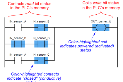
The logic of the STL language applies across a very important bit that is called RLO (Result of Logic Operation). This bit is responsible for scanning the status of the code Lines and passes that logic to the process outputs.
So here we are getting into how to make these instructions, at first you have to know that there are two ways to initiate a memory bit in the code logic, they are just slightly different but in general, they can handle the same function.
Note: We are discussing these programming using Siemens Tia Portal.
Assign Instruction (=)
Format
= < Bit > // used for a BOOL data type (I, Q, M, L, D)
Description
= <Bit> writes the RLO into the addressed bit for a switched-on master control relay if MCR = 1. If MCR = 0, then the value 0 is written to the addressed bit instead of RLO.
So if the conditions status (RLO) is true the assigned bit will be true, but if any of those conditions will be not true the assigned bit will be in the false state.
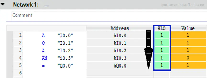
Example
For the next Fig you can see that all of the input conditions (RLO) are achieved so the output Q0.0 is turned to be in the True state.
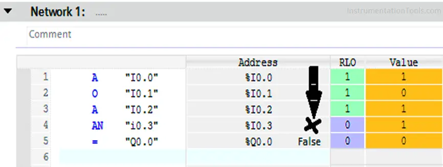
Unlike what we can see here in Line No. (4) the value of I0.3 becomes 1 and this value is NOT ANDED with the previous values.
So the RLO becomes false at this line and by its role the assigned output Q0.0 also becomes false.
SET Instruction
Format
S < Bit > // the data type is Bool
Description
S (set bit) places a “1” in the addressed bit if RLO = 1 and the switched-on master control relay MCR = 1.
But If RLO = 0, then the addressed bit does not change and it will remain True.
RESET Instruction
Format
R < Bit > // the data type is Bool
Description
R (reset bit) places a “0” in the addressed bit if RLO = 1 and master control relay MCR = 1.
But If RLO = 0, then the addressed bit will not be changed and it will remain in the false state.
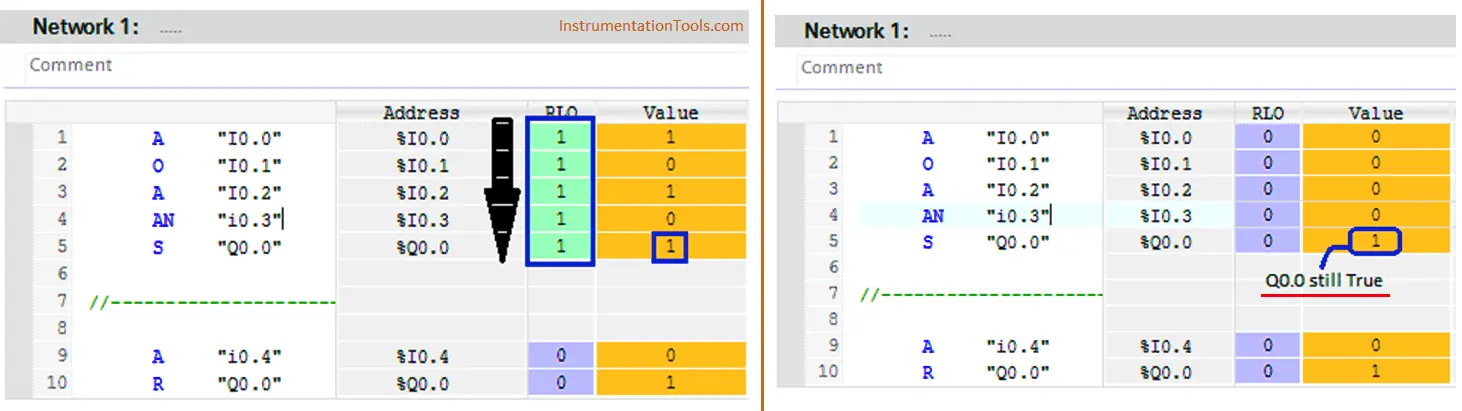
Example for SET & RESET Instructions
Here you can see that all the conditions are achieved and the output Q0.0 is launched. (Left side image)
And after that when the RLO returns to be Zero, the output bit Q0.0 retains its value till the Reset instruction is launched. (Right side image)
Here we are launching the Reset instruction by turn I0.0 ON to make Q0.0 false again.
Notice that also however I0.0 returns to Zero the output Q0.0 would retain its value (False).
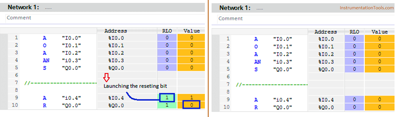
Right-side image -> when reset bit is activated. Left-side image -> after the reset.
Summary
So, as we said before we can use both methods to handle the same function but with the Assign method you do not need a Reset function as the assigned bit would return to Zero once just one of the conditions is not achieved, unlike the SET & RESET method if the conditions are achieved, the output bit will be launched and it will not return to zero till the Reset instruction is activated, Even the conditions return to Zero the output bit Q0.0 will retain its value (1) till you reset the bit.
If you liked this article, then please subscribe to our YouTube Channel for PLC and SCADA video tutorials.
You can also follow us on Facebook and Twitter to receive daily updates.
Read Next: