The IR method of measuring gas concentration is based on the absorption of IR radiation at certain wavelengths as the radiation passes through a volume of the gas.
IR hydrocarbon gas detectors can be classified into two types known as point detectors and open path detectors.
For point detectors, the absorption path length is fixed, and is determined by the instrument design to be a few inches.
For the open path IR detectors, the absorption path length can be as long as 130 meters as opposed to the few inches of the point detector. Instruments based on IR technology use two wavelengths, one at the gas absorbing wavelength and the other at a wavelength not absorbed by the gas; neither wavelength is absorbed by the other atmospheric constituents such as water vapor, nitrogen, oxygen, or carbon dioxide.
Fig : Open Path Infrared Gas Detector
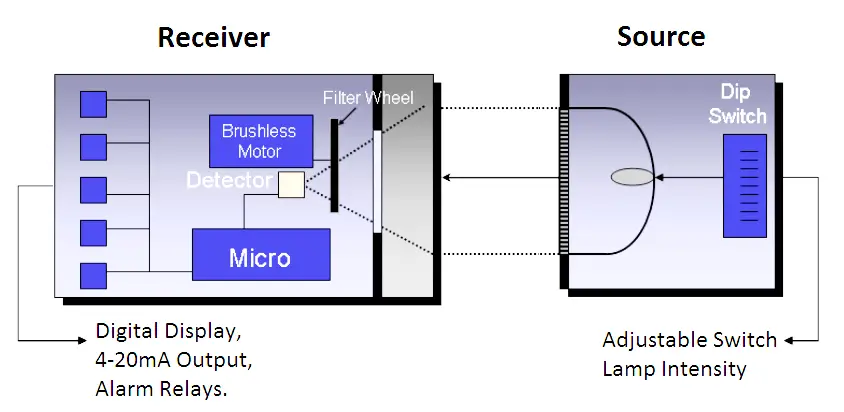
Image Credits : General Monitors
IR gas sensing technology provides for fail-to-safe operation in contrast to electrocatalytic sensors since optical sensing is an active technology, which continuously monitors for sensor faults and communicates them to the user.
This is achieved chiefly through the use of the second or reference wavelength. IR detectors are also immune to poisoning, resistant to corrosion, can operate in a deficit or surplus of oxygen, and do not suffer from reduction in sensor life on repeated exposure to gas.
With the sophisticated optical and electronic designs currently being used, the detectors are factory calibrated and virtually maintenance free.
This is particularly desirable when sensors must be located in inaccessible areas and cannot be easily calibrated on a periodic basis.
Point IR Detectors
Point combustible gas detectors are used to monitor the presence of flammable levels of hydrocarbon gas or vapor in industrial environments such as refineries and chemical plants.
If the concentration of the hydrocarbon gas or vapor exceeds its Lower Explosive Level (LEL), the gas can be ignited and lead to an explosion.
Point combustible gas detectors are therefore located at several dozen sites to monitor for gas leaks.
In the point IR detector, the concentration of hydrocarbon gas is measured via the infrared absorption of an optical beam known as the active beam.
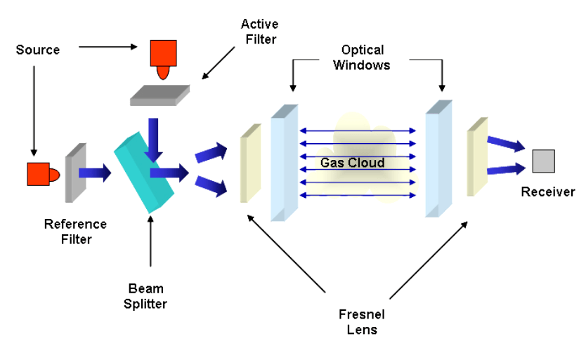
Image Credits : General Monitors
A second optical beam known as the reference follows the same optical path as the active but contains radiation at a wavelength not absorbed by the gas.
This second beam provides for the fail-to-safe operation of the point IR detector; a feature that is not available with the electrocatalytic technology.
The two wavelengths are generated by two infrared sources which have the active and reference filters attached to them, are pulsed alternately and guided by the optics onto a common optical path.
A detector receives the two optical pulses after they have traversed the optical absorption path.
All the components of the instrument are mounted inside an explosion-proof housing with infrared transparent optical windows.
Maintenance on IR detectors is typically limited to periodic cleaning of the external optical windows and reflectors to ensure dependable performance.
The current availability of reliable, low cost electronics and solid state IR detectors have reduced costs and made the technology feasible for many commercial applications.
The signals from the IR detector are converted into digital format and processed by a microprocessor with the help of a gas concentration lookup table and a correction factor for ambient temperature variations.
The instrument outputs a 4-20 mA analog signal as well as a RS485 serial output. Use of the RS485 using the MODBUS RTU protocol provides two-way addressable communication for status, alarm, fault, and other information for operation, trouble shooting, or programming the unit. MODBUS also permits linking of up to 128 point detectors in series and up to 247 point detectors using repeaters.
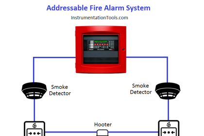
A typical system configuration linking 20 gas detectors and 20 flame detectors is shown in Fig
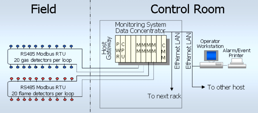
Fig : Multi-drop Addressable System
Point IR Detectors Vs Open Path IR Detectors
In open path IR gas detectors, the concepts of the point IR detector are expanded to a gas sampling path which can be as long as 130 meters as opposed to a few inches internal to the instrument.
These systems can either use a retro-reflector or use separate IR transmitters and receivers housed in explosion-proof housings.
The active and reference wavelengths for hydrocarbon detection are alternately selected via a rotating filter wheel, while the source is a broadband IR emitter.
Open path IR detectors offer many of the same advantages as the point IR technology such as immunity to poisons, high sensitivity leak detection, low maintenance, fail-to-safe detection, and easy installation.
Unlike point gas detectors, open path IR detectors do not pinpoint the location of a leak since the leak can occur anywhere along the optical path.
The gas concentration output for open path detectors is therefore expressed in ppm.meters or LEL.meters since only the product of the average gas concentration and gas cloud length can be calculated.
This means that a small dense cloud of hydrocarbon gas could give the same output as a large dispersed cloud if the integral of the gas concentration over the path length were the same.
A unique feature is a dual range, ppm.m for small hydrocarbon leaks and LEL.m for more catastrophic leaks, with the ability to switch between ranges as required.
Open path systems are particularly useful in those situations where a gas release has been dispersed by wind or natural diffusion.
The gas can still be detected, even though its point concentration may have fallen below normal alarm settings for point detectors.
If a gas leak creates a cloud, it generally has the following characteristics:
- The highest gas concentration of a cloud is at the source and it decreases in concentration towards the edges.
- The shape of the gas cloud is elongated or has an irregular pattern, depending upon air currents.
- In outdoor environments gas clouds dissipate more quickly and can have very low gas concentrations
Open path systems have the advantage of being able to cover large open areas, a line of several potential leak sources such as a row of valves or pumps, and also for perimeter monitoring of leaks.
A mirror can also be used to deflect the optical beam around a corner to the receiver. Whereas hydrocarbon detection systems use relatively inexpensive components and are used to monitor larger leaks, more expensive diode laser based systems are currently available that can monitor toxic gases such as hydrogen fluoride and hydrogen sulfide at low ppm.meter levels.
Source : General Monitors


Hye Sir,
Thank you for the information regarding the point and path IR gas detector. I am interesting to know more about the point gas detector. Currently, I am doing a research on the placement of the gas detector. Based on my knowledge, IR gas detector is using a measuring chamber to calculate the LEL and UEL of the flammable gas. However, I found many gas detector layouts that have a coverage circle. May you explain more regarding the coverage circle? How they determine the coverage circle? Is that a cone of vision? But as far as I know, the cone of vision is only applicable for fire/flame detector.