Inst ToolsInst ToolsInst Tools
  • Courses
  • Automation
    • PLC
    • Control System
    • Safety System
    • Communication
    • Fire & Gas System
  • Instrumentation
    • Design
    • Pressure
    • Temperature
    • Flow
    • Level
    • Vibration
    • Analyzer
    • Control Valve
    • Switch
    • Calibration
    • Erection & Commissioning
  • Interview
    • Instrumentation
    • Electrical
    • Electronics
    • Practical
  • Q&A
    • Instrumentation
    • Control System
    • Electrical
    • Electronics
    • Analog Electronics
    • Digital Electronics
    • Power Electronics
    • Microprocessor
  • Request
Search
  • Books
  • Software
  • Projects
  • Process
  • Tools
  • Basics
  • Formula
  • Power Plant
  • Root Cause Analysis
  • Electrical Basics
  • Animation
  • Standards
  • 4-20 mA Course
  • Siemens PLC Course
Reading: How to do Turbine Flow Meter Verification?
Share
Notification Show More
Font ResizerAa
Inst ToolsInst Tools
Font ResizerAa
  • Courses
  • Design
  • PLC
  • Interview
  • Control System
Search
  • Courses
  • Automation
    • PLC
    • Control System
    • Safety System
    • Communication
    • Fire & Gas System
  • Instrumentation
    • Design
    • Pressure
    • Temperature
    • Flow
    • Level
    • Vibration
    • Analyzer
    • Control Valve
    • Switch
    • Calibration
    • Erection & Commissioning
  • Interview
    • Instrumentation
    • Electrical
    • Electronics
    • Practical
  • Q&A
    • Instrumentation
    • Control System
    • Electrical
    • Electronics
    • Analog Electronics
    • Digital Electronics
    • Power Electronics
    • Microprocessor
  • Request
Follow US
All rights reserved. Reproduction in whole or in part without written permission is prohibited.
Inst Tools > Blog > Flow Measurement > How to do Turbine Flow Meter Verification?

How to do Turbine Flow Meter Verification?

Turbine flow meter can be calibrated by placing the flow meter in series with a meter prover which has a known or base volume. Visit Instrumentation Tools.

Last updated: November 2, 2023 10:14 am
Editorial Staff
Flow Measurement
No Comments
Share
2 Min Read
SHARE

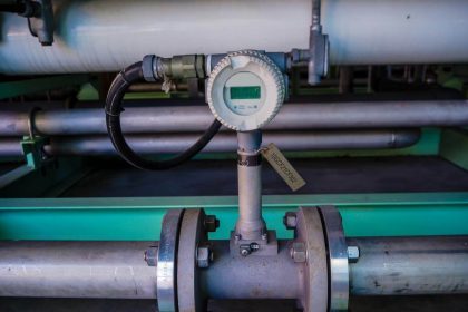
We have a turbine flow meter, gas chromatograph & flow computer installed at our site, and similar units are installed at the GAIL terminal also.

Contents
Turbine Flow Meter VerificationBasic Diagram

How metering can be done with these two setups? GAIL (gas distribution company) people used to do turbine flow meter calibration, is it possible to do calibration on-site for a turbine-type flow meter? Please let me know the procedure if any.

Turbine Flow Meter Verification

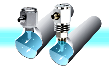
No calibration is done on a Turbine flow meter. The meter can only verified or proved against a standard reference measurement.

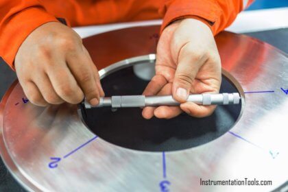
Meter proving is a physical test used to determine the accuracy and performance of the meters.

The turbine meter can be proved by placing the meter in series with a meter prover which has a known or base volume in such a way that the fluid measured by the meter is also measured by the prover.

Turbine Flow Meter Verification

Regardless of the prover or meter type, the basic proving principle is as follows

Turbine Flow Meter K Factor Formula

The above needs to be updated in the Flow computer. Gas chromatograph will provide the online gas composition which can be used to calculate the molecular weight and Specific gravity of the fluid being measured.
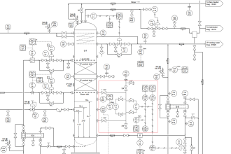
Basic Diagram

 A basic diagram of a meter proving is described below:

Turbine Flow Meter Calibration

For more information, kindly refer to compact provers from Emerson and API chapter 4 which covers the proving of meters.

Author: Arunbalaji Baskar

If you liked this article, then please subscribe to our YouTube Channel for Instrumentation, Electrical, PLC, and SCADA video tutorials.

You can also follow us on Facebook and Twitter to receive daily updates.

Read Next:

  • Factors in Flow Measurement
  • Practical Calibration Standards
  • Flumes Flow Measurement
  • Process Control Loop Testing
  • Flow Meters in a Laboratory
Don't Miss Our Updates
Be the first to get exclusive content straight to your email.
We promise not to spam you. You can unsubscribe at any time.
Invalid email address
You've successfully subscribed !

Continue Reading

How to Select a Rotameter? – Parameters and Applications
Hot Wire Anemometer Principle and Types
Transit Time Flow Meter Principle
Difference between Orifice & Restriction Orifice
Area Velocity Flow Meter Principle
Oval Gear Flow Meters – Principle, Advantages, Animation
Share This Article
Facebook Whatsapp Whatsapp LinkedIn Copy Link
Share
Leave a Comment

Leave a Reply Cancel reply

Your email address will not be published. Required fields are marked *

Stay Connected

128.3kFollowersLike
69.1kFollowersFollow
210kSubscribersSubscribe
38kFollowersFollow

Categories

Explore More

Paddle Wheel Flow Meters – Principle, Advantages, Limitations
Coriolis Mass Flow Meter as a Multi-Variable Transmitter
Short Notes on Differential Pressure Flow Meters
What is a Vortex Flow Meter?
Basics of Flow Measurement
Interview Questions on Flow Measurement
What is Integral Flow Orifice Assembly?
Mass Flow Meters

Keep Learning

Flow Meter Questions and Answers

Flow Meter Questions and Answers

Differential Pressure and Pressure Loss

What is Differential Pressure and Pressure Loss?

Advantages and Disadvantages of Flow Measurement Techniques

Advantages & Disadvantages of Different Flow Meters

Oscillating Piston Flow Meters Animation

Oscillating Piston Flow Meters Working Principle

Reciprocating Piston Meters

Overview of Positive Displacement Flow Meters

Venturi Flow Meter

Venturi Flow Meter – Working Principle, Advantages, Animation

Turbine Flow Meter Animation

Turbine Flow Meter – Principle, Advantages, Disadvantages

Metering components to measure flow of Natural gas

Is it Easy to Measure Natural Gas Flow and Volume?

Learn More

Understanding RS-485 Communication

Understanding RS-485 Communication

PLC to PLC Communication using S7 Connection

PLC to PLC Communication using S7 Connection PUT & GET Instructions

Cascade-Temperature-Control-System

Cascade Temperature Control System

Dry Leg

Calculate 0%, 50%, and 100% Calibration Points for ΔP transmitter

Timer STL Programming

Timers using Statement List (STL) PLC Programming

Ash Handling System in Thermal Power Plant

Ash Handling System in Thermal Power Plant

InTouch SCADA Password Protection

InTouch SCADA Login Password Security

Comparison of Proportional Integral Derivative Controllers (PID)

Comparison of Proportional Integral Derivative Controllers (PID)

Menu

  • About
  • Privacy Policy
  • Copyright

Quick Links

  • Learn PLC
  • Helping Hand
  • Part Time Job

YouTube Subscribe

Follow US
All rights reserved. Reproduction in whole or in part without written permission is prohibited.
Welcome Back!

Sign in to your account

Username or Email Address
Password

Lost your password?