Split Range Control Loop is used, where there are several manipulated variables, but a single output variable. The coordination among different manipulated variables is carried out by using Split Range Control.
Split Range Control Loop
The split range control loop can be implemented in three different ways.
They are
- Split Range Control
- Sequence Control
- Opposite Acting Control
Also Read : What is a Control Loop ?
Split Range Control
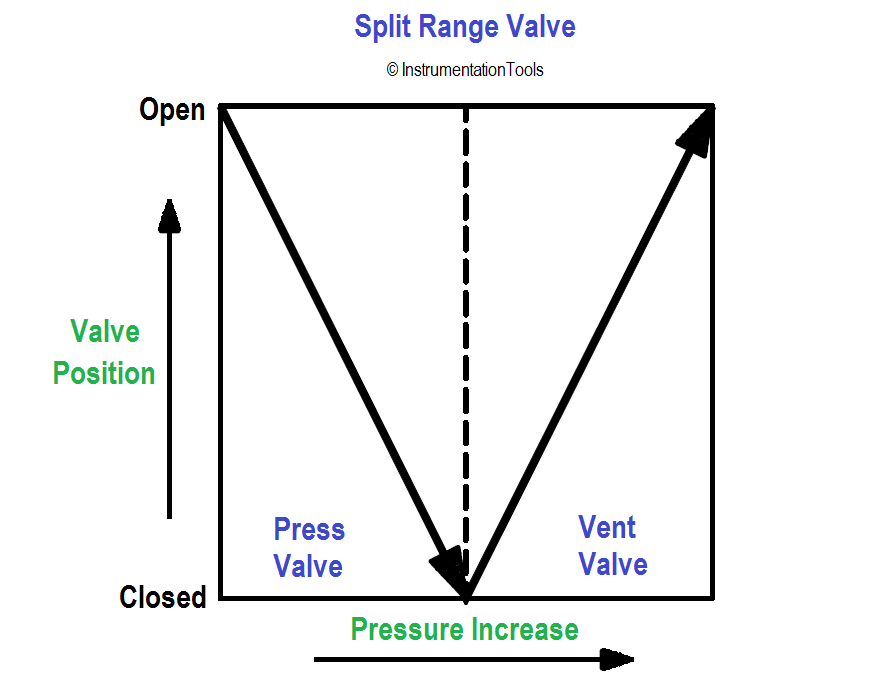
some control loops have two control valves on the output signal of one controller.
For example with two control valves, one valve pressurizes and the other vents a vessel.
A plot shows the valve position verses pressure.
it is important to keep the control loop gain constant for good split range operation. the gain of each valve (including the process) must be made similar. otherwise limit cycling or poor control will result.
Example :
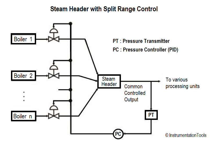
Fig. shows an example of a typical split range control scheme. The steam discharges from several boilers are combine at a steam header. Overall steam pressure at the header is to be maintained constant through a pressure control loop.
The command from the pressure controller is used for controlling simultaneously the steam flow rates from the boilers in parallel. Clearly, there is a single output variable (steam header pressure) while there are a number of manipulating variables (discharge from different boilers).
Also Read : Exclusive Control Valve Sequence
Sequence Control
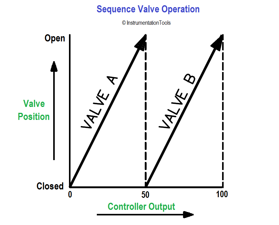
Where sequence valve operation is called for, they are intended to work as follows:
In this sequence valve operation, Valve A will open from 0 to 100% when the PID controller output is 0 to 50%.
When PID controller output reaches 50% then valve A will be 100% open and then Valve B will start opening after 50% of PID output. So Valve B will open from 0 to 100% for the PID controller output 50 to 100%.
Read Split Range Control Questions : Check Here
Opposite Acting Control
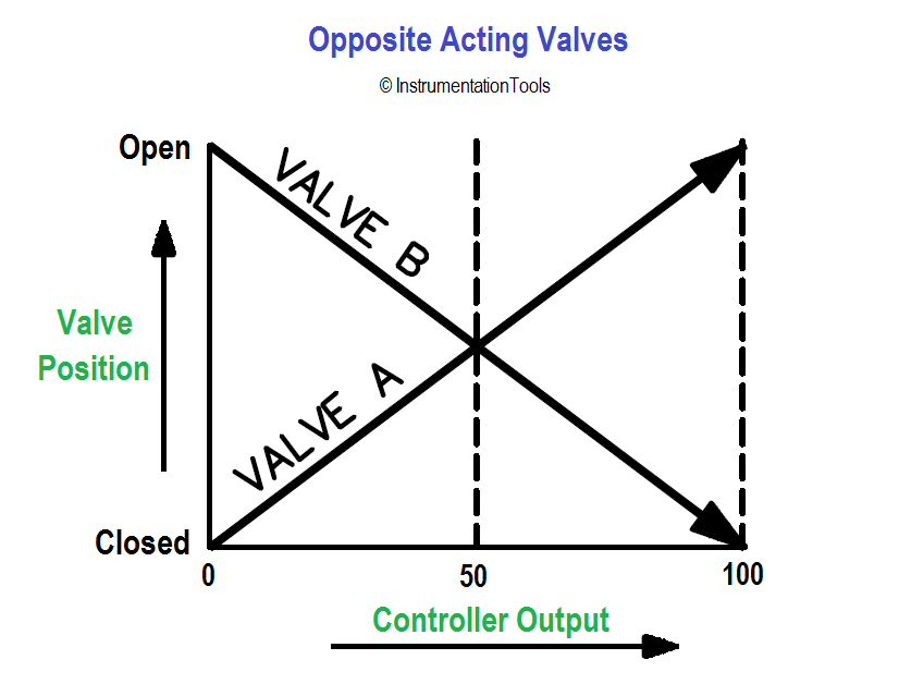
Opposite Acting Valves control loop noted as opposite acting valves have the following action.
In this Opposite acting valves applications, Valve A will start open from 0 to 100% for the PID controller output of 0 to 100% and simultaneously Valve B will close from 100% to 0% for the same PID controller output.
Also Read : Control Valve Sequence Methods

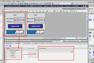

HOW WE CAN SIMULATE sequence valve operation IN TIA PORTAL