Inst ToolsInst ToolsInst Tools
  • Courses
  • Automation
    • PLC
    • Control System
    • Safety System
    • Communication
    • Fire & Gas System
  • Instrumentation
    • Design
    • Pressure
    • Temperature
    • Flow
    • Level
    • Vibration
    • Analyzer
    • Control Valve
    • Switch
    • Calibration
    • Erection & Commissioning
  • Interview
    • Instrumentation
    • Electrical
    • Electronics
    • Practical
  • Q&A
    • Instrumentation
    • Control System
    • Electrical
    • Electronics
    • Analog Electronics
    • Digital Electronics
    • Power Electronics
    • Microprocessor
  • Request
Search
  • Books
  • Software
  • Projects
  • Process
  • Tools
  • Basics
  • Formula
  • Power Plant
  • Root Cause Analysis
  • Electrical Basics
  • Animation
  • Standards
  • 4-20 mA Course
  • Siemens PLC Course
Reading: Solenoid Valve Failure in Plant Start-Up: Identifying the Root Cause
Share
Font ResizerAa
Inst ToolsInst Tools
Font ResizerAa
  • Courses
  • Design
  • PLC
  • Interview
  • Control System
Search
  • Courses
  • Automation
    • PLC
    • Control System
    • Safety System
    • Communication
    • Fire & Gas System
  • Instrumentation
    • Design
    • Pressure
    • Temperature
    • Flow
    • Level
    • Vibration
    • Analyzer
    • Control Valve
    • Switch
    • Calibration
    • Erection & Commissioning
  • Interview
    • Instrumentation
    • Electrical
    • Electronics
    • Practical
  • Q&A
    • Instrumentation
    • Control System
    • Electrical
    • Electronics
    • Analog Electronics
    • Digital Electronics
    • Power Electronics
    • Microprocessor
  • Request
Follow US
All rights reserved. Reproduction in whole or in part without written permission is prohibited.
Inst Tools > Blog > Control Valves > Solenoid Valve Failure in Plant Start-Up: Identifying the Root Cause

Solenoid Valve Failure in Plant Start-Up: Identifying the Root Cause

Discover key factors behind solenoid valve failures at plant start-ups. Learn root cause analysis methods for efficient, reliable operations.

Last updated: November 28, 2023 12:10 pm
vicky
Control Valves Root Cause Analysis (RCA) Solenoid Valve
1 Comment
Share
6 Min Read
SHARE

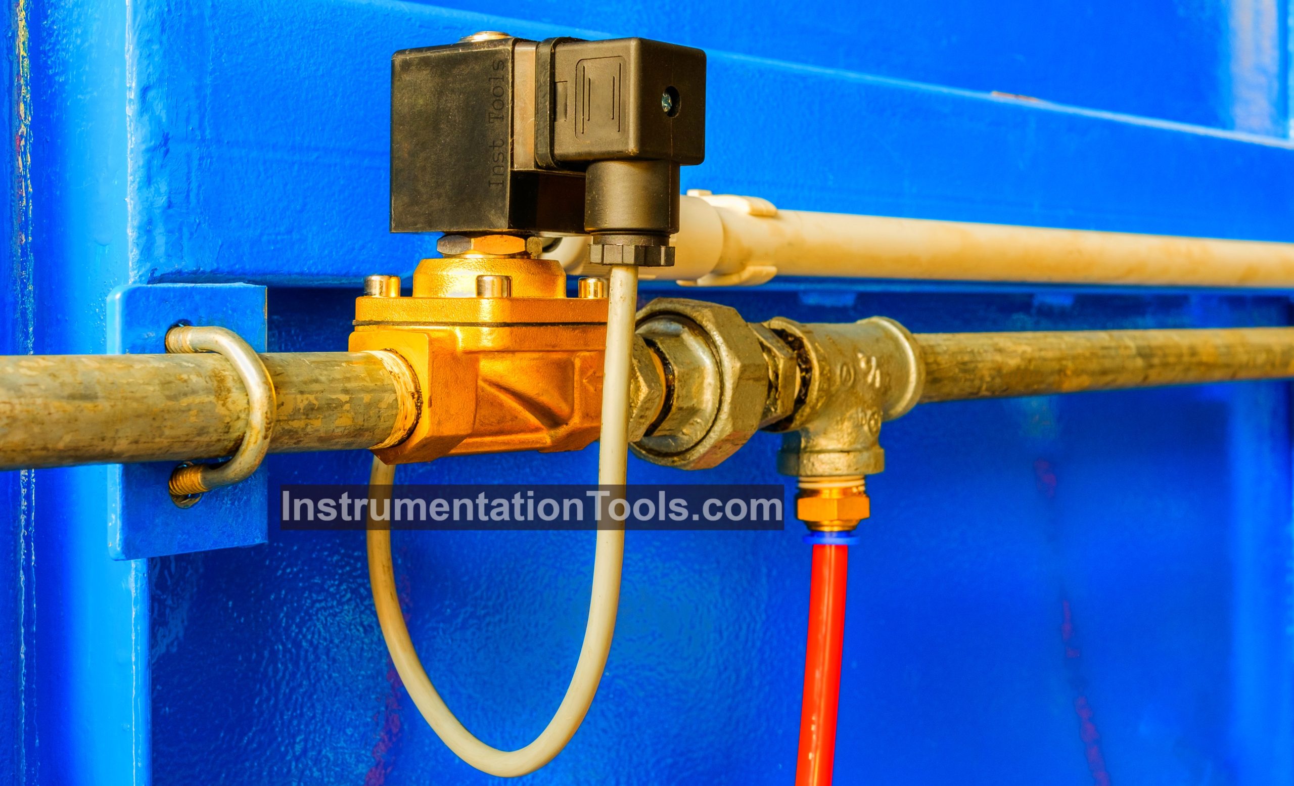
In this article, we are going to discuss one root cause analysis in which a Solenoid solenoid-operated valve (SOV) did not open while start-up of the plant. This article is an interesting one.

Contents
Solenoid Valve Failure in Plant Start-UpObservations of the Operation & Maintenance TeamInstrumentation Engineer ActivitiesRoot Cause AnalysisRecommendations

Solenoid Valve Failure in Plant Start-Up

After the shutdown of the Nitrogen plant in one unit of a refinery, a start-up was planned.

In the start-up procedure, if the product nitrogen’s purity comes within spec, then the product is diverted to the main nitrogen header by opening a final product on-off valve.

Till then, the product is being vented because it is not in proper specs.

Solenoid Valve Failure in Plant Start-Up

During start-up, the specs of the nitrogen were within the limit. So, the panel engineer gave the open command to the final product on-off valve to divert the product nitrogen to the main header. But the valve did not open and a command vs feedback error was generated.

The panel engineer gave the close command and then again gave the open command to the valve. But the valve did not open. So, he informed instrumentation engineers to check the valve.

The on-off valve was a single-acting valve with a fail condition close. The instrumentation team checked and solved the issue within an hour. Then after stroke checking, the on-off valve was taken inline.

Observations of the Operation & Maintenance Team

During the start-up procedure, when the purity of the nitrogen reached the acceptable limit, the panel engineer gave the open command to the final product on-off valve which diverts the nitrogen to the main header. But the valve did not open.

The panel engineer tried one more time but still, the valve did not open. So, the Instrumentation team was informed about this and they visited the field.

Instrumentation Engineer Activities

The following activity was done by the Instrumentation team in the field

  1. Checked supply voltage to the SOV. The supply voltage was ok.
  2. The actuator was checked for passing issues. The actuator was found ok.
  3. Valve operation is checked by giving direct air to check the valve body’s condition. Valve operation was smooth.
  4. Disconnected the tubing connecting the actuator and SOV (while open command is present). But no air was coming.
  5. Checked the resistance of the solenoid valve (SOV) and found that the resistance was 5600 ohm.

The instrumentation team replaced the SOV’s coil and the issue was resolved.

Also, on checking the records, it was found that the preventive maintenance (PM) of this valve was done 5 days before the incident. In PM no observation came and the valve operation was ok.

Root Cause Analysis

A fault tree analysis was made for this incident which is shown below:

Root Cause Analysis of Solenoid Valve Failure in Plant Operations

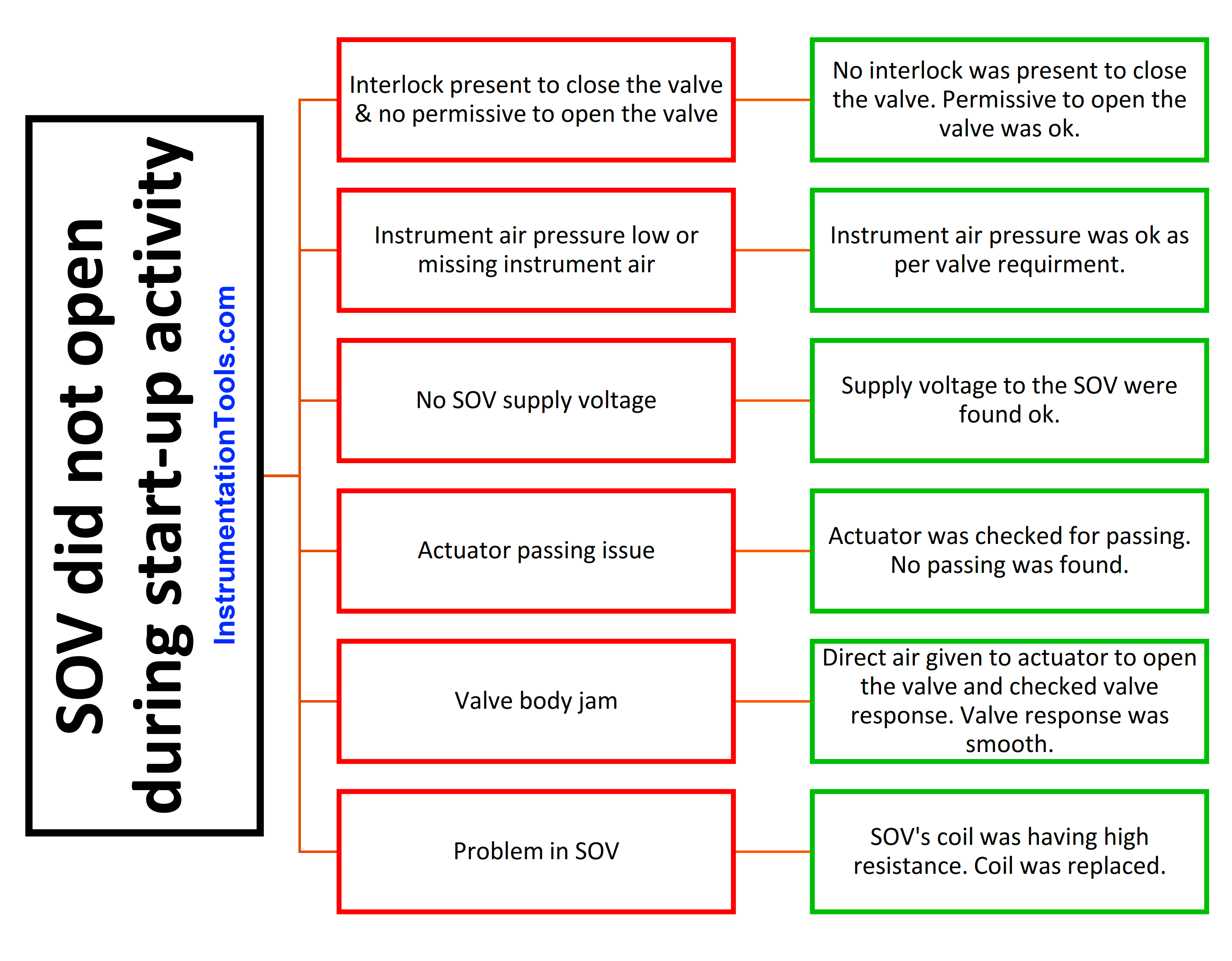
As mentioned in the above fault tree analysis, the valve did not open due to the SOV coil having an issue.

Various reasons mentioned below were considered and a conclusion was made. The reasons are:

  • The valve did not have any active interlock to close it. Also, permissive to open the valve was ok.
  • Instrument air pressure was checked and was found ok as per valve requirement.
  • Supply voltage to the SOV in the field was also ok.
  • Actuator was also ok and no passing was present.
  • Valve was operated by giving direct air to check the body’s condition. The valve operation was smooth.
  • SOV’s coil was checked and found that the coil’s resistance was higher than normal. It was 5900 as compared to 55 ohms.

Here, SOV’s coil was not in healthy condition and hence the valve was not opening.

Recommendations

2 recommendations came after this incident. These recommendations should be implemented in every plant.

Recommendation 1: In PM activity of a valve, always check the resistance of the SOV coil. In this case, the resistance might have increased gradually over time. This could have been identified in the PM activity if coil resistance checking was done.

Recommendation 2: In LLF activity, check the SOV’s temperature. Abnormally high temperature of SOV indicates that the coil is heating and action needs to be taken.

If you liked this article, then please subscribe to our YouTube Channel for PLC and SCADA video tutorials.

You can also follow us on Facebook and Twitter to receive daily updates.

Read Next:

  • Control Valve Maintenance
  • How to Install a Control Valve?
  • Motor Operated Valve Problems
  • Solenoid and Motorized Valves
  • The Valve Problems and Solutions
Don't Miss Our Updates
Be the first to get exclusive content straight to your email.
We promise not to spam you. You can unsubscribe at any time.
Invalid email address
You've successfully subscribed !

Continue Reading

Difference between Quick Opening, Linear & Equal Percentage Control Valve characteristics
Types of Pilot Operated Diaphragm Solenoid Valve Principle
Control Valve Sequence Methods
Dampers and Louvres
Centrifugal Compressor Outage Reduced – Root Cause Analysis
Speed of Actuators
Share This Article
Facebook Whatsapp Whatsapp LinkedIn Copy Link
Share
1 Comment
  • Sattar says:
    July 13, 2024 at 6:33 pm

    its excellent troubleshooting. i have one question that how can we measure the resistance of of SOV coil during normal PM and plant running conditions. we can’t measure the resistance of live electrical equipment, until we disconnect the cable. if we want to measure the resistance of sov coil then valve will be go to fail safe condition. normally its not recommended to check resistance because it will also affect process side

    Reply

Leave a Reply Cancel reply

Your email address will not be published. Required fields are marked *

Stay Connected

128.3kFollowersLike
69.1kFollowersFollow
210kSubscribersSubscribe
38kFollowersFollow

Categories

Explore More

Basics of Control Valve Sizing
None Could Repair Slightly Damaged Magnetic Flow Meter Flow Tube
What is a Float Control Valve? Types, Advantages, Disadvantages
JT Valve Working Principle
What is Complementary Split Range Control (CSRC)?
Cavitation Test Setup
Concept of Steam Conditioning Valves
Miscellaneous Electrical Tasks – Repaired Reformer Tubes Weld Stress Relief

Keep Learning

Rupture Disc

Rupture Discs bursts caused too many Urea Plant Shutdowns

Needle Valve Schematic

How Needle Valve Works ?

What is Travel Stop in Control Valve

What is Travel Stop in Control Valve?

Plant Air Storage Tank

Plant Air Storage Tank Pressure Fluctuations Root Cause Analysis

Control Valves Basic Theory

Control Valves Theory

CO2 Stripper Old Differential Pressure Transmitter Stopped Working

CO2 Stripper Old Differential Pressure Transmitter Stopped Working

What is a Servo Valve?

What is a Servo Valve? – Principle and Advantages

Weigh Feeder Drive

Failing Weigh Feeders and Mechanical Variable Speed Drives (VSD)

Learn More

State Variable Analysis and Design

Concepts of State, State Variables & State Model

WirelessHART field instruments

WirelessHART device Configuration

Alternative Optical Proximity Sensor

Proximity Sensor

DC motor speed control

DC Motor Speed Control

Silicon Carbide Lightning Arresters Working Principle

Stability in Frequency Domain

Time Domain Analysis

Power Electronics Objective Questions

Single-Phase Half Wave AC-DC Converter Quiz

Counters and Timers Projects Using Analog Electronic Devices

Top 100 Counters and Timers Projects Using Analog Electronic Devices

Menu

  • About
  • Privacy Policy
  • Copyright

Quick Links

  • Learn PLC
  • Helping Hand
  • Part Time Job

YouTube Subscribe

Follow US
All rights reserved. Reproduction in whole or in part without written permission is prohibited.
Welcome Back!

Sign in to your account

Username or Email Address
Password

Lost your password?