One of the best Automation vendors all over the world is Siemens, this good reputation was not formed by chance, one of the main reasons for this reputation is its software programming environment TIA Portal (Totally Integrated Automation).
The advantage of this program is the integration of all Siemens components, using this software you will be able to:
- Configuring the hardware of your project.
- Establishing the whole network of the system.
- Programming of PLC with different languages.
- Designing of SCADA & HMI systems.
- Simulation of your projects.
- Finally, the scope of our article that this software could really offer a great feature to ease the troubleshooting of your Automation system.
Types of Software Faults
The software faults or errors could be divided into two categories:
Logic Error (Programming)
These types of errors cause abnormal behavior and actions for the system, it is caused due to some programming mistakes, it could be wrong addressing of the I/O signals or it may be some mistakes with the ladder logic itself, the bad news that it should be detected by the programmer with himself the software will not be able to determine these types of errors where it is.
However, these errors could be traced by going online with the PLC and check the rungs as we will see.
Compiling Error (System)
On the other hand, we might find these errors which are caused by some programming mistakes that the compiler of the software can not accept it, the good news is that these errors are detected by the compiler of the software.
Also, we can use the Diagnostic buffer that saves all the events that happened with the PLC and it is really a great tool for troubleshooting.
Also Read: PLC Hardware Troubleshooting Steps
How to Deal with PLC Programming Faults?
These faults mostly occurred at the commissioning phase, as you just finished writing your code and you are going to try your logic with the real field.
It is very normal to find out some mistakes through your code, and the best way to overcome such a situation is to go online with the PLC.
Steps to go Online through your PLC
- The first thing that you need to do is connecting your PC/PG with the PLC through an Ethernet cable to establish the physical layer of the network.
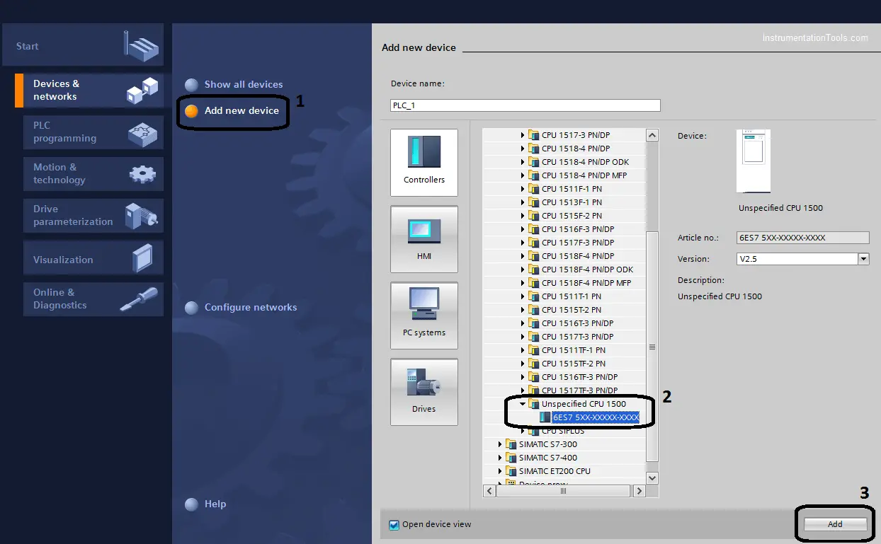
- Then you have to go through TIA Portal and open a new project and select unspecified 1500 CPU as shown in the next figure. (Note if you already know the CPU No. you can choose it directly)
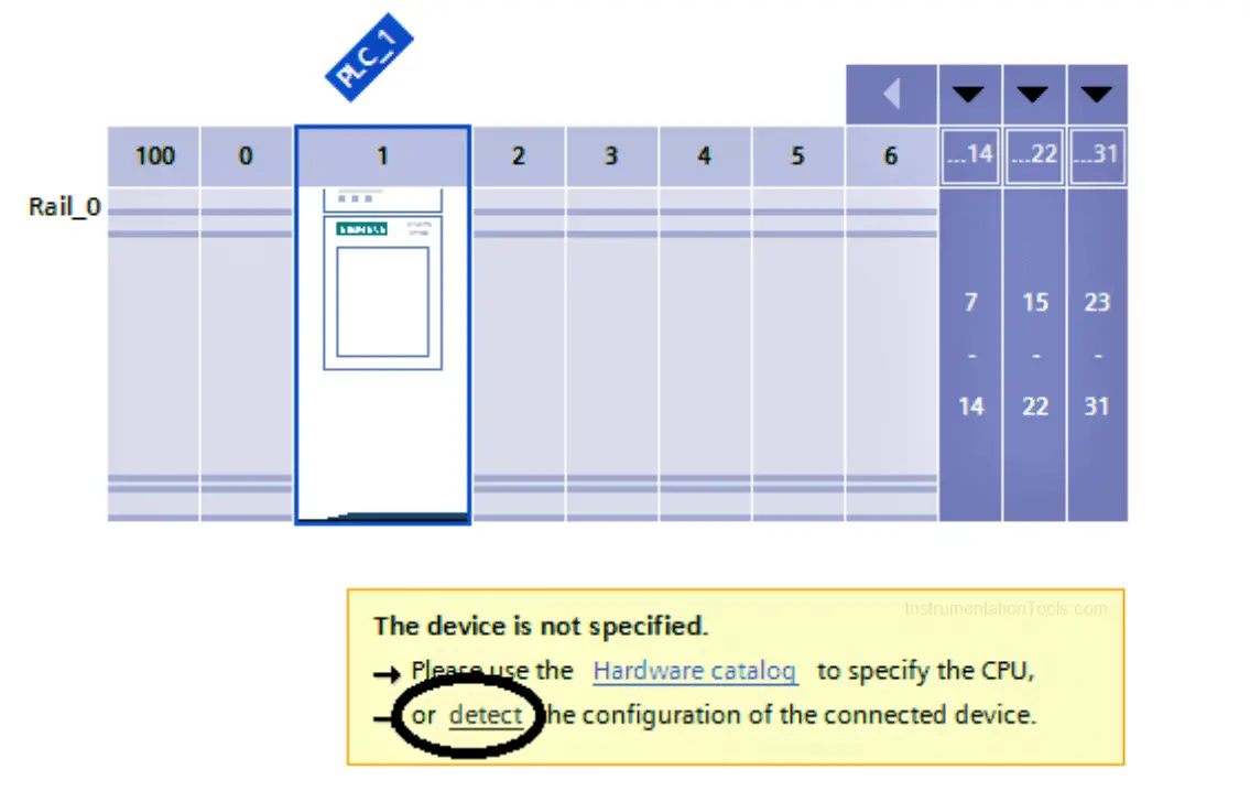
- The next step is to detect the hardware configuration of your station.
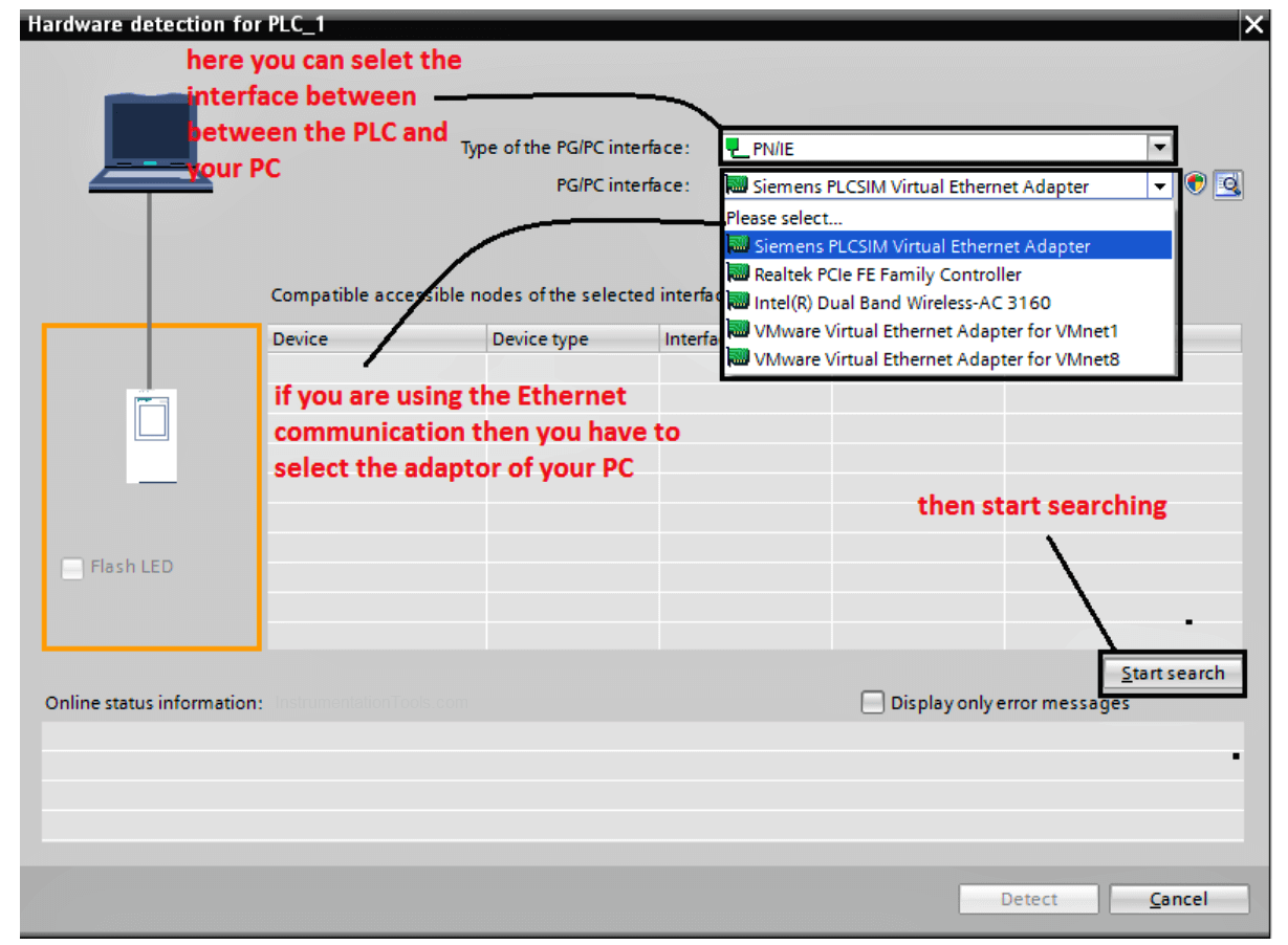
- If you are using an Ethernet connection make sure that the IP of the PLC and your PC at the same subnet, then after searching about the PLC select the device and press detect.
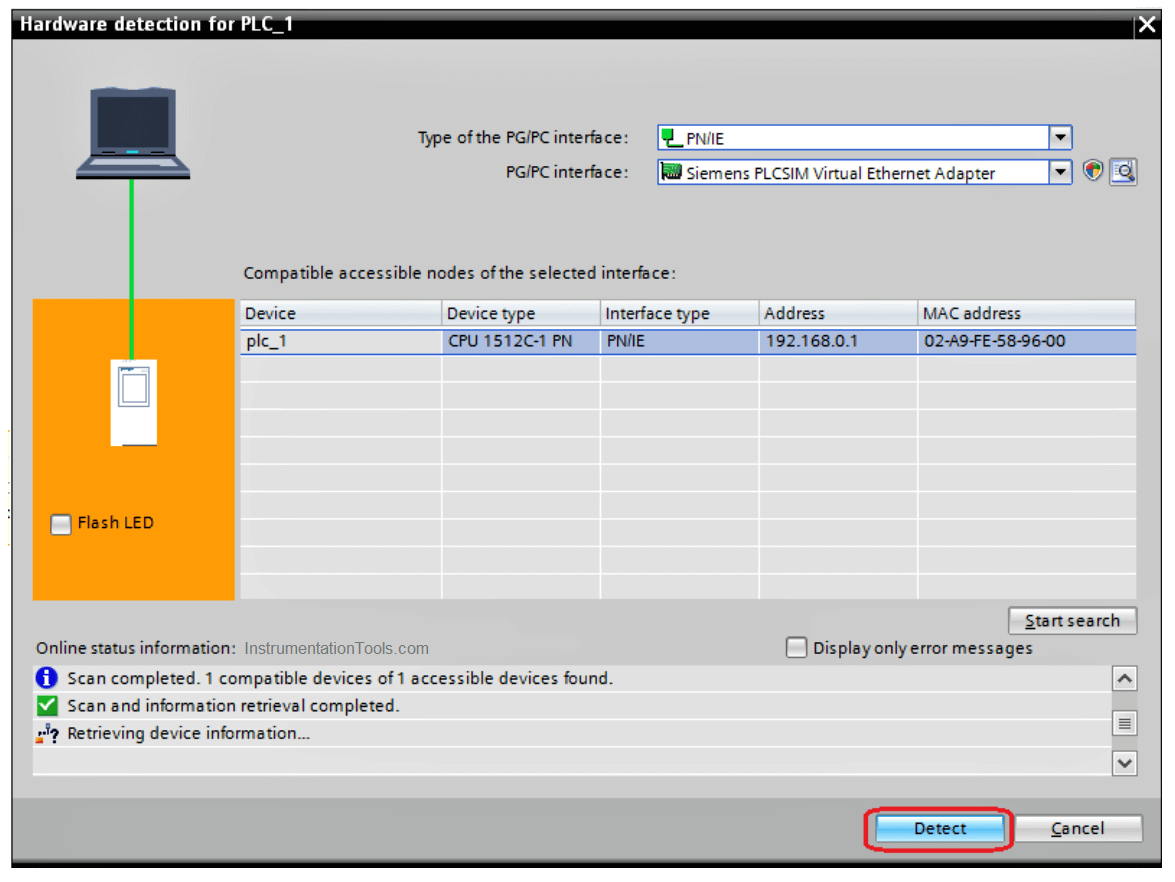
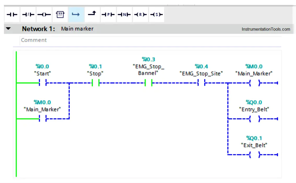
- Here and after selecting the PLC you have to go online with your code to see what is going into your logic visually, that would really help a lot to track the problem.

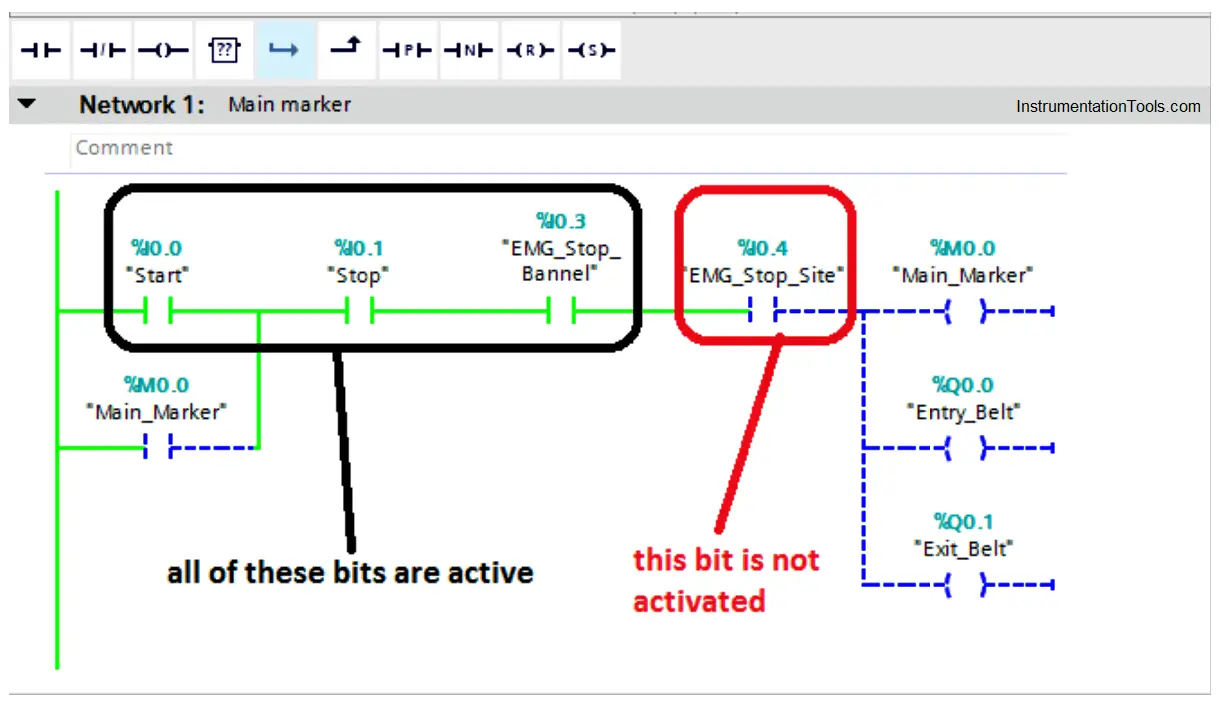
- Now we are online with our PLC to know why the process is not running even we are pressing on the start push button.
- As we can see it is too easy to trace the activated and deactivated bits from the ladder logic, the green bit is activated and the blue dashed one is not activated.
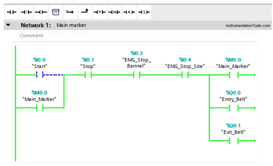
- After going to the Emergency stop at the site and activate it, now we can see all of the branch is correctly operated.
How to Deal with Compiling Errors in PLC?
By using the TIA portal software, it is too easy to identify and detect the compiling faults, as the program points at the errors by identifying a detailed location of the error.
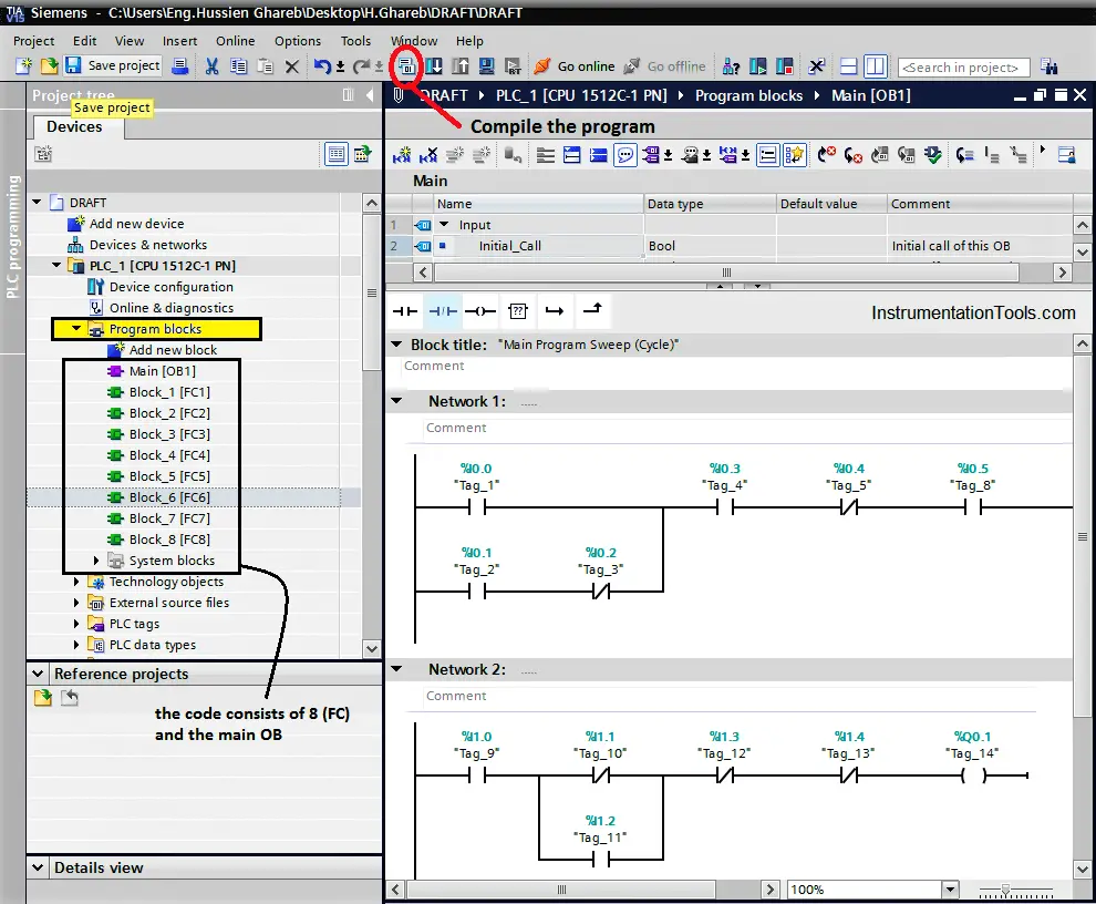
For the next figure, we can see a simple code that consists of some functions and the main OB, by compiling the code from the sign below, a compiling window will appear and it will check all the program networks to detect any type of errors.
Note: Before compiling the code, you have to ensure that you select the whole program blocks not just the main OB, that by pressing on the program blocks below that is shown with yellow color.
Here is the window that defines the type of the error and its detailed location, we can see that we have three compiling errors at Function (6) at Networks (1 & 2).

Notice that you can go to the invalid network manually or you just can click on the network and the function would open automatically and it will point to the faulty network.
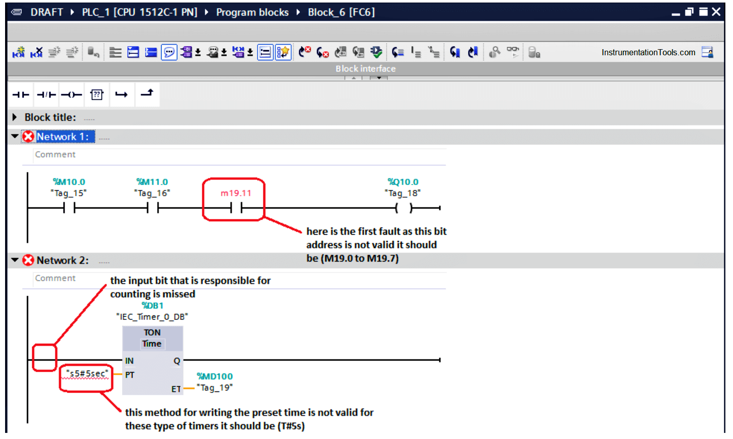
After going to the desired function, we will find the three faults as shown in the next figure:
- It is clear for us about the first fault that the byte (19) should have just eight bits so it can be addressed as M (19.0 – 19.1 – 19.2 – 19.3 – 19.4 – 19.5 – 19.6 – 19.7).
- Here for the second rung we can notice that there are two faults the first one is there is no an assigned input that would make the timer count.
There must be a bit at the timer input that is responsible for timer counting.
- Also, for the second rung you can notice the preset time is written into wrong way.
The right way to insert the preset time for such timers is that (T#5s)
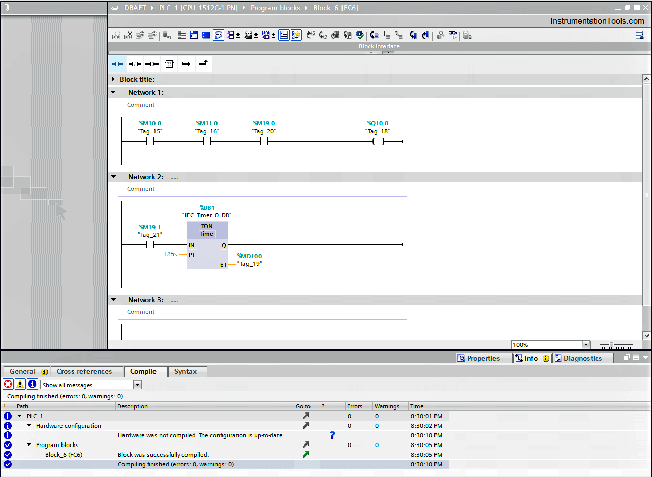
So, by editing our code and fixing the faults, we can compile it again to ensure that is healthy.
In the next article, we will discuss a very important tool that helps a lot with troubleshooting which is the Diagnostic Buffer so stay tuned and wait for it.
If you liked this article, then please subscribe to our YouTube Channel for Instrumentation, Electrical, PLC, and SCADA video tutorials.
You can also follow us on Facebook and Twitter to receive daily updates.
Read Next:
- Yokogawa DCS Tutorials
- PLC System Cabinet Health Checks
- Communication Protocols in PLC
- SFC Language in PLC Programming
- Difference between PLC and Computers

