If sets of wires lie too close to one another, electrical signals may “couple” from one wire (or set of wires) to the other(s). This can be especially detrimental to signal integrity when the coupling occurs between AC power conductors and low-level instrument signal wiring such as thermocouple or pH sensor cables.
Two mechanisms of electrical “coupling” exist: capacitive and inductive. Capacitance is a property intrinsic to any pair of conductors separated by a dielectric (an insulating substance), whereby energy is stored in the electric field formed by voltage between the wires. The natural capacitance existing between mutually insulated wires forms a “bridge” for AC signals to cross between those wires, the strength of that “bridge” inversely proportional to the capacitive reactance (XC = 1/2πfC ). Inductance is a property intrinsic to any conductor, whereby energy is stored in the magnetic field formed by current through the wire. Mutual inductance existing between parallel wires forms another “bridge” whereby an AC current through one wire is able to induce an AC voltage along the length of another wire.
Capacitive coupling between an AC power conductor and a DC sensor signal conductor is shown in the following diagram:
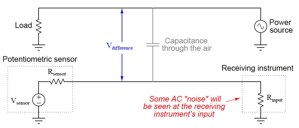
If the voltage-generating sensor happens to be a thermocouple and the receiving instrument a temperature indicator, the result of this capacitive coupling will be a “noisy” temperature signal interpreted by the instrument. This noise will be proportional to both the voltage and the frequency of the AC power.
Inductive coupling between an AC power conductor and a DC sensor signal conductor is shown in the following diagram: + Vsensor – Rsensor
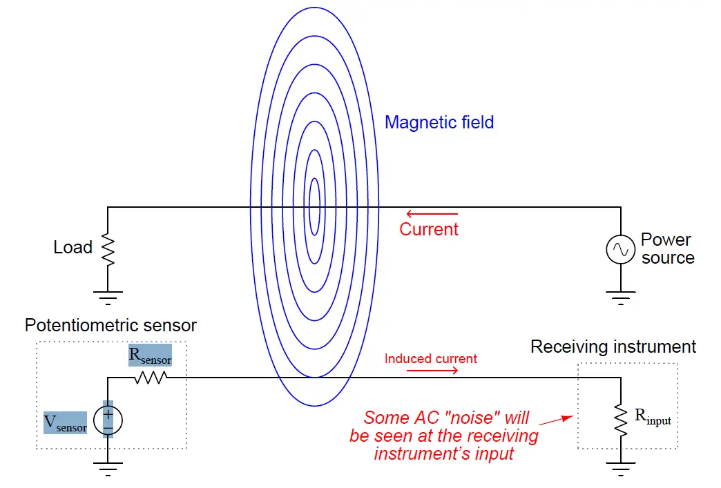
Whereas the amount of noise induced into a low-level signal via capacitive coupling was a function of voltage and frequency, the amount of noise induced into a signal via inductive coupling is a function of current and frequency.
A good way to minimize signal coupling is to simply separate conductors carrying incompatible signals. This is why electrical power conductors and instrument signal cables are almost never found in the same conduit or in the same ductwork together. Separation decreases capacitance between the conductors (recall that C = Ae/d where d is the distance between the conductive surfaces). Separation also decreases the coupling coefficient between inductors, which in turn decreases mutual inductance (recall that M = k√(L1L2) where k is the coupling coefficient and M is the mutual inductance between two inductances L1 and L2). In control panel wiring, it is customary to route AC power wires in such a way that they do not lay parallel to low-level signal wires, so that both forms of coupling may be reduced.
If conductors carrying incompatible signals must cross paths, it is advisable to orient the conductors perpendicular to each other rather than parallel, like this:
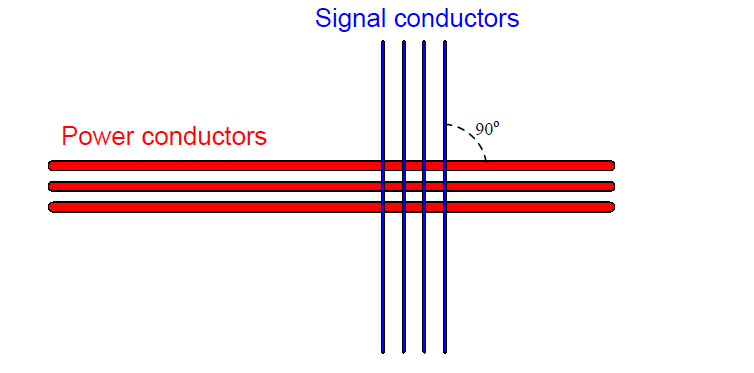
Perpendicular conductor orientation reduces both inter-conductor capacitance and mutual inductance by two mechanisms. Capacitance between conductors is reduced by means of minimizing overlapping area (A) resulting from the perpendicular crossing. Mutual inductance is reduced by decreasing the coupling coefficient (k) to nearly zero since the magnetic field generated perpendicular to the current-carrying wire will be parallel and not perpendicular to the “receiving” wire. Since the vector for induced voltage is perpendicular to the magnetic field (i.e. parallel with the current vector in the “primary” wire) there will be no voltage induced along the length of the “receiving” wire.
The problem of power-to-signal line coupling is most severe when the signal in question is analog rather than digital. In analog signaling, even the smallest amount of coupled “noise” corrupts the signal. A digital signal, by comparison, will become corrupted only if the coupled noise is so great that it pushes the signal level above or below a detection threshold it should not cross. This disparity is best described through illustration.
Two signals are shown here, coupled with equal amounts of noise voltage:
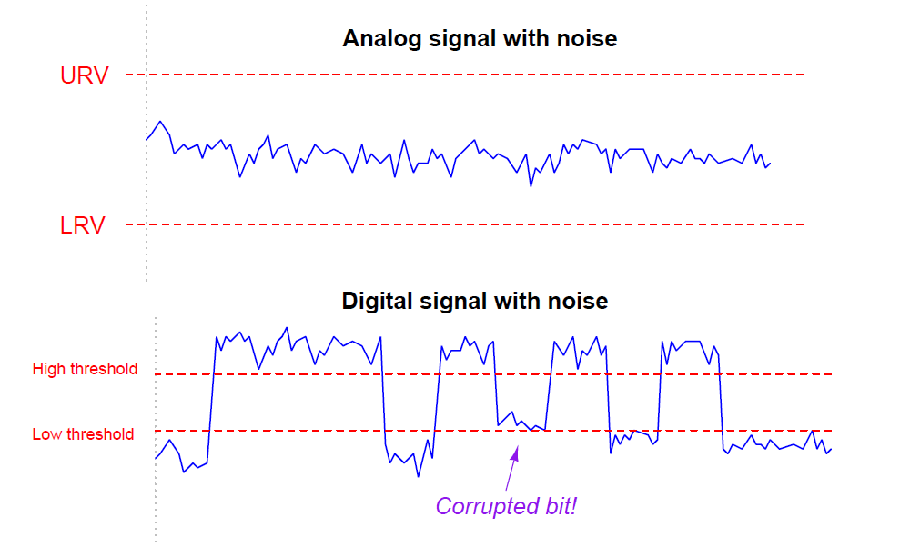
The peak-to-peak amplitude of the noise on the analog signal is almost 20% of the entire signal range (the distance between the lower- and upper-range values), representing a substantial degradation of signal integrity. Analog signals have infinite resolution, which means any change in signal amplitude has meaning. Therefore, any noise whatsoever introduced into an analog signal will be interpreted as variations in the quantity that signal is supposed to represent.
That same amount of noise imposed on a digital signal, however, causes no degradation of the signal except for one point in time where the signal attempts to reach a “low” state but fails to cross the threshold due to the noise. Other than that one incident represented in the pulse waveform, the rest of the signal is completely unaffected by the noise, because digital signals only have meaning above the “high” state threshold and below the “low” state threshold. Changes in signal voltage level caused by induced noise will not affect the meaning of digital data unless and until the amplitude of that noise becomes severe enough to prevent the signal’s crossing through a threshold (when it should cross), or causes the signal to cross a threshold (when it should not).
From what we have seen here, digital signals are far more tolerant of induced noise than analog signals, all other factors being equal. If ever you find yourself in a position where you must route a signal wire near AC power conductors, and you happen to have the choice whether it will be an analog signal (e.g. 4-20 mA, 0-10 V) or a digital signal (e.g. EIA/TIA-485, Ethernet), your best option is to choose the digital signal to coexist alongside the AC power wires.