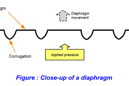
A pressure switch is one detecting the presence of fluid pressure. Pressure switches often use diaphragms or bellows as the pressure-sensing element, the motion of which actuates one or more switch contacts.
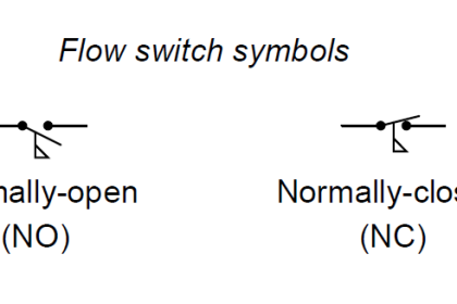
Recall from Basics of Switches article, that the “normal” status of a switch is the resting condition of no stimulation. A pressure switch will be in its “normal” status when it senses minimum pressure (e.g. an applied pressure, or in some cases a vacuum condition). For a pressure switch, “normal” status is any fluid pressure below the trip threshold of the switch.
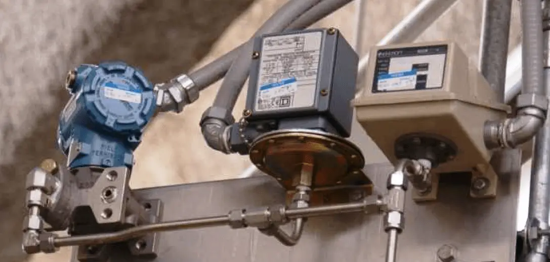
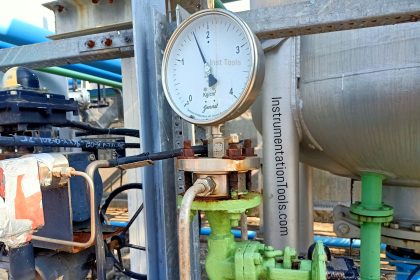
 The following photograph shows two pressure switches sensing the same fluid pressure as an electronic pressure transmitter (the device on the far left) because they are all plumbed to a common tube:
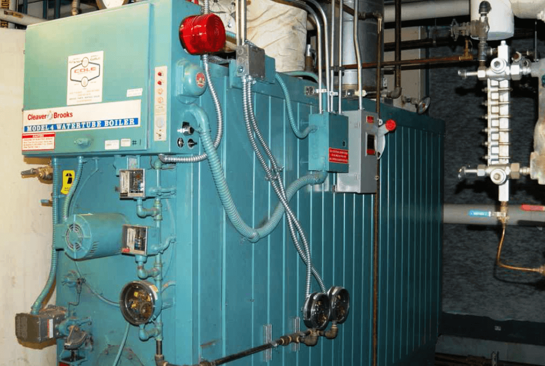
A legacy design of pressure switch uses a bourdon tube as the pressure-sensing element, and a glass bulb partially filled with mercury as the electrical switching element. When applied pressure causes the bourdon tube to flex sufficiently, the glass bulb tilts far enough to cause the mercury to fall against a pair of electrodes, thus completing an electrical circuit. A great many pressure switches of this design were sold under the brand name of “Mercoid,” with a few appearing in this photograph of a steam boiler (the round-shaped units with glass covers allowing inspection of the bourdon tube and mercury tilt switch):
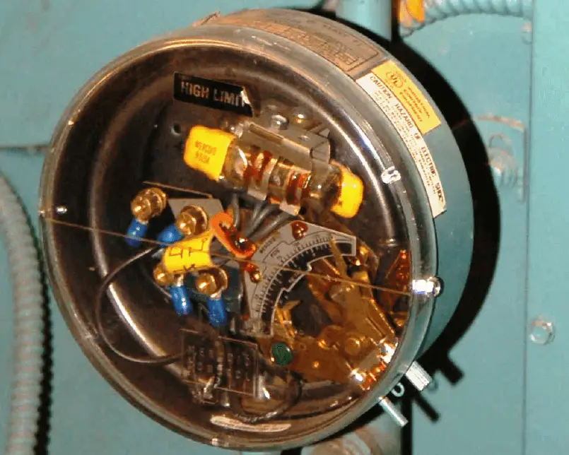
A close-up photograph of one of these pressure switches appears here. The bourdon tube is grey in color, and almost as wide in diameter as the circular switch housing. The mercury tilt switch bottles have yellow-colored plastic caps covering up their external electrical contacts:
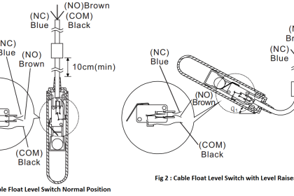
The next set of photographs show a mercury tilt switch removed from the pressure switch mechanism, so you may see the switch in two different states (contact open on the left, and closed on the right):
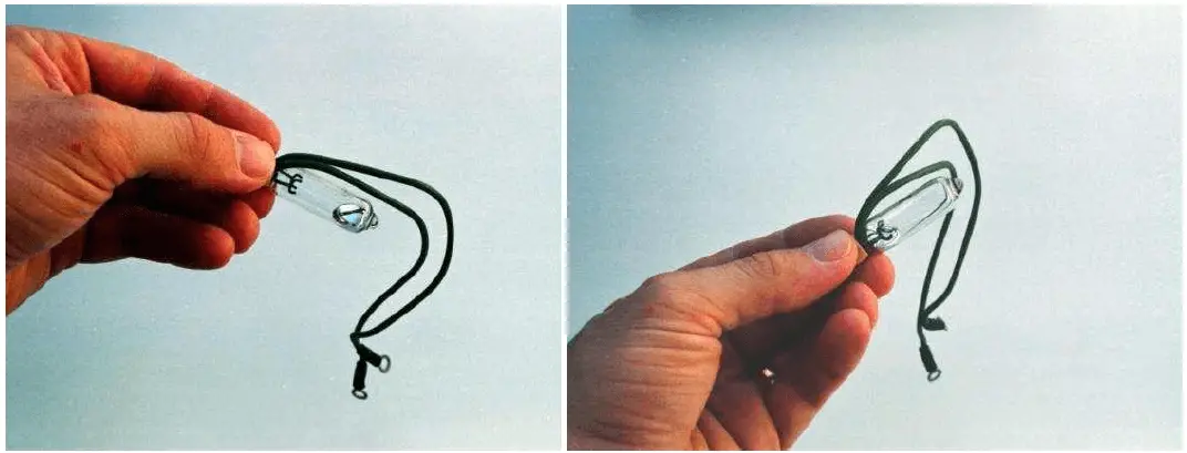
Advantages of mercury tilt switches include immunity to switch contact degradation from harmful atmospheres (oil mist, dirt, dust, corrosion) as well as safety in explosive atmospheres (since a spark contained within a hermetically sealed glass bulb cannot touch off an explosion in the surrounding atmosphere). Disadvantages include the possibility of intermittent electrical contact resulting from mechanical vibration, as well as sensitivity to mounting angle (i.e. you would not want to use this kind of switch aboard a moving vehicle!).
A pressure switch manufactured by the Danfoss corporation appears in the next photograph. This particular model of pressure switch has windows on the front cover allowing a technician to see the pressure limit setting inside:
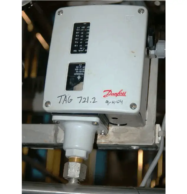
This switch balances the force generated by a pressure-sensing element against a mechanical spring. Tension on the spring may be adjusted by a technician, which means the trip point of this switch is adjustable.
One of the settings on this switch is the deadband or differential pressure setting, seen in the lower window. This setting determines the amount of pressure change required to re-set the switch to its normal state after it has tripped. For example, a high-pressure switch with a trip point of 67 PSI (changes state at 67 PSI, increasing) that re-sets back to its normal state at a pressure of 63 PSI decreasing has a “deadband” or “differential” pressure setting of 4 PSI (67 PSI − 63 PSI = 4 PSI).
The “differential” pressure setting of a gauge pressure switch is not to be confused with a true differential pressure switch. In the next photograph, we see a pressure switch truly actuated by differential pressure (the difference in fluid pressure sensed between two ports):
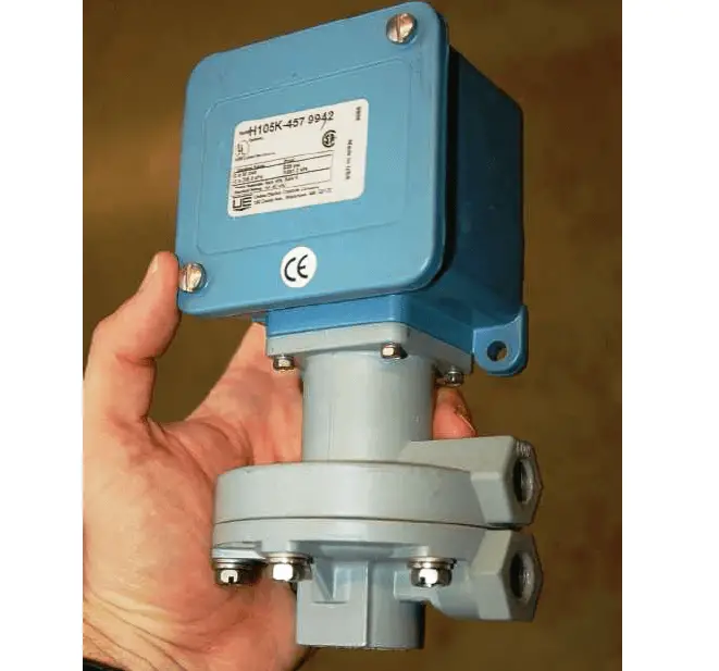
The electrical switch element is located underneath the blue cover, while the diaphragm pressure element is located within the grey metal housing. The net force exerted on the diaphragm by the two fluid pressures varies in magnitude and direction with the magnitude of those pressures. If the two fluid pressures are precisely equal, the diaphragm experiences no net force (zero differential pressure).
Like the Danfoss gauge pressure switch seen previously, this differential pressure switch has a “trip” or “limit” setting as well as a “dead-band” or “differential” setting. It is important to recognize and clearly distinguish the two meanings of differential pressure in the context of this device. It senses differences in pressure between two input ports (“differential pressure” – the difference between two different fluid pressure connections), but being a switch, it also exhibits some dead band in its action (“differential pressure” – a change in pressure required to re-set the switch’s state).


In our application we need to trip a double diaphragm air operated pump at high and low pressure detected by pressure switch. Do we need two pressure switches or both high and low pump trip can be achieved by a single pressure switch.
You need either two pressure switches or one pressure transmitter, choose as per your application and budget.