Inst ToolsInst ToolsInst Tools
  • Courses
  • Automation
    • PLC
    • Control System
    • Safety System
    • Communication
    • Fire & Gas System
  • Instrumentation
    • Design
    • Pressure
    • Temperature
    • Flow
    • Level
    • Vibration
    • Analyzer
    • Control Valve
    • Switch
    • Calibration
    • Erection & Commissioning
  • Interview
    • Instrumentation
    • Electrical
    • Electronics
    • Practical
  • Q&A
    • Instrumentation
    • Control System
    • Electrical
    • Electronics
    • Analog Electronics
    • Digital Electronics
    • Power Electronics
    • Microprocessor
  • Request
Search
  • Books
  • Software
  • Projects
  • Process
  • Tools
  • Basics
  • Formula
  • Power Plant
  • Root Cause Analysis
  • Electrical Basics
  • Animation
  • Standards
  • 4-20 mA Course
  • Siemens PLC Course
Reading: Siemens Pressure Transmitter with Remote Seals Calculations
Share
Font ResizerAa
Inst ToolsInst Tools
Font ResizerAa
  • Courses
  • Design
  • PLC
  • Interview
  • Control System
Search
  • Courses
  • Automation
    • PLC
    • Control System
    • Safety System
    • Communication
    • Fire & Gas System
  • Instrumentation
    • Design
    • Pressure
    • Temperature
    • Flow
    • Level
    • Vibration
    • Analyzer
    • Control Valve
    • Switch
    • Calibration
    • Erection & Commissioning
  • Interview
    • Instrumentation
    • Electrical
    • Electronics
    • Practical
  • Q&A
    • Instrumentation
    • Control System
    • Electrical
    • Electronics
    • Analog Electronics
    • Digital Electronics
    • Power Electronics
    • Microprocessor
  • Request
Follow US
All rights reserved. Reproduction in whole or in part without written permission is prohibited.
Inst Tools > Blog > Formulas > Siemens Pressure Transmitter with Remote Seals Calculations

Siemens Pressure Transmitter with Remote Seals Calculations

Last updated: May 4, 2019 9:41 am
Editorial Staff
Formulas Level Measurement
2 Comments
Share
4 Min Read
SHARE

Remote seals of sandwich design are fitted between the connection flange of the measuring point and a dummy flange. Remote seals of flange design are fitted directly on the connection flange of the measuring point. The respective pressure rating of the dummy flange or the flanged remote seal must be observed.

Contents
Offset of measuring rangePressure transmitter outputInfluence of ambient temperatureTypes of installation for pressure and level measurements (open vessels)Types of installation for absolute level measurements (closed vessels)Type of installation for differential pressure and flow measurementsTypes of installation for level measurements (closed vessels)

The pressure transmitter should be installed below the connection flange (and below the lower connection flange in the case of differential pressure transmitters). This arrangement must be used in the low-pressure range.

When measuring at pressures above atmospheric, the pressure transmitter can also be installed above the connection flange.

The capillaries between the remote seal and the pressure transmitter should be as short as possible to obtain a good transmission response.

Offset of measuring range

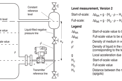
If there is a difference in height between the two connection flanges when measuring with two remote seals, an additional differential pressure will result from the oil filling of the remote seal capillaries. This results in a measuring range offset which has to be taken into account when you set the pressure transmitter.

An offset in the measuring range also occurs when combining a remote seal with a transmitter if the remote seal is not installed at the same height as the transmitter.

Pressure transmitter output

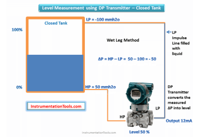
If the level, separation layer or density increase in closed vessels, the differential pressure and hence the output signal of the pressure transmitter also increase.

For an inverted relationship between the differential pressure and the output signal, the start-of-scale and full-scale values of the SITRANS P (transmitter) must be interchanged.

With open vessels, a rising pressure is usually assigned to an increasing level, separation layer or density.

Influence of ambient temperature

Temperature differences between the individual capillaries and between the individual remote seals should be avoided. Temperature variations in the area of the measuring setup cause a change in volume of the filling liquid and hence measuring errors.

Notes

  • For the separation layer measurement, the separation layer has to be positioned between the two spigots. Also you must make sure that the level in the container is always above the top spigot.
  • When measuring density, make sure that the level of the medium remains constant. The level should be above the top spigot.

The following figures showing calculation formulae for different measurements like level, separation (interface), and density measurements for both Open & Closed Tanks using Remote Seal Type Pressure/Differential Pressure Transmitters.

In below figures : PMA & PME are nothing but LRV & URV of a transmitter.

Types of installation for pressure and level measurements (open vessels)

Level Measurement using Capillary Pressure Transmitters

Types of installation for absolute level measurements (closed vessels)

absolute level measurements principle

Type of installation for differential pressure and flow measurements

differential pressure and flow measurements

Types of installation for level measurements (closed vessels)

level measurement using Remote Seal Pressure Transmitters

Capillary Remote Seal Level Measurement

Reference  : Siemens Manual

Articles You May Like :

Hybrid Level Measurement

DP Transmitter Applications

DP Transmitters Compensation

Pressure Gauges Chemical Seals

Segmental Wedge Flow Meter

Don't Miss Our Updates
Be the first to get exclusive content straight to your email.
We promise not to spam you. You can unsubscribe at any time.
Invalid email address
You've successfully subscribed !

Continue Reading

Paddle Wheel Level Switch Principle
DP Transmitters Level Measurement Principle Video
Types of Level Gauges
Radiation based Level Sensor Principle
Pressure Transmitters Leg Compensation Technique
Identify Characteristics of Level Measurement Technologies
Share This Article
Facebook Whatsapp Whatsapp LinkedIn Copy Link
Share
2 Comments
  • nazim mirza says:
    March 15, 2018 at 11:14 am

    I have some confusion about Hu .it will be zero always or not ,how we select this .kindly brief me about this

    Reply
  • pvasudevan says:
    October 13, 2020 at 10:08 pm

    Dear Sir,

    pressure ma calculation and temperature ma calculation pls

    Reply

Leave a Reply Cancel reply

Your email address will not be published. Required fields are marked *

Stay Connected

128.3kFollowersLike
69.1kFollowersFollow
210kSubscribersSubscribe
38kFollowersFollow

Categories

Explore More

Torque Tube Level Measurement Principle
Weight-based Level Measurement Principle
How Buoyant Force instruments Works ?
How to Install Ultrasonic Level Transmitters
Differential Pressure Level Transmitter Errors
Bubbler Level Measurement Animation
Sounding Level Transmitter Working Animation
DP Level Transmitters Compensation Techniques

Keep Learning

Field Instrument 4-20mA Calculation

How to do 4-20mA Conversions Easily

Zero Suppression in level Measurement

Zero Suppression and Zero Elevation Calculations

Asymmetric capillary for Level Measurement

Effects of Symmetric and Asymmetric Capillary Tube Pressure Measurement

Process-Variable-to-Percentage-Conversion

Formula for Process Variable to Percentage Conversion

Scaling Sensor Output to Engineering Units

Scaling Sensor Output to Engineering Units

Capacitive Tank Gauges

Capacitive Tank Gauges

DP Transmitter Level Measurement for Closed Tank Wet leg Method

DP Transmitter Dry Leg & Wet Leg Calculations

Closed Tank Non-Zero-Based Direct Mount Application

Open and Closed Tank Level Calculations

Learn More

PLC Program to Operate Stamping of Parts

PLC Application for Stamping Operation – Example Programming

PLC Programming Limit Switch

PLC Programming Example using Limit Switch

Difference Between Regenerative and Dynamic Braking

Difference Between Regenerative and Dynamic Braking

Target Flow Transmitter Problem

Unreliable Ammonia Flow Transmitter Reading and Problems

6 Pieces of Essential Equipment For PCB Assembly

6 Pieces of Essential Equipment For PCB Assembly

Sugar Industry Logics

Mill Interlocks in the Sugar Industry

PLC Program for Daily Production Record

PLC Program for Daily Production Record

Reed Switch Principle

Reed switch Working Principle

Menu

  • About
  • Privacy Policy
  • Copyright

Quick Links

  • Learn PLC
  • Helping Hand
  • Part Time Job

YouTube Subscribe

Follow US
All rights reserved. Reproduction in whole or in part without written permission is prohibited.
Welcome Back!

Sign in to your account

Username or Email Address
Password

Lost your password?