There are many ways where PLCs can communicate and talk to each other, in this article we will talk about one of these methods which is how to establish Siemens communication between PLCs using the i-device function to make PLC-to-PLC data transfer.
What is the I-Device function?
The I-Device function can be used to exchange data between two PLCs very easily. An I-Device is simply a PLC that is used as an IO device. That means the PLC will act as an IO module providing inputs and receiving outputs with the other PLC.
I-device function enables PROFINET to communicate not only with subordinate devices like IO controllers, but also IO communication with other higher-level or central controllers as an IO device.
Siemens Communication between PLCs
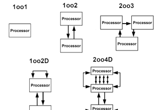
Most of the S7 family PLCs support the I-Device feature but some controllers don’t depending on the firmware version for example:
- S7-300 (from firmware version V3.2)
- S7-1200 (from firmware version V4)
You can simply know if your controller has the I-device feature or not by going into your PLC PROFINET interface properties and checking for the “operating mode” option. See pictures 1a and 1b.
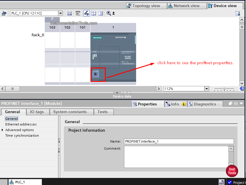
picture 1a. PLC doesn’t support I-device
From the picture, we can’t see the “operating mode” option, so we know that PLC doesn’t support the I-device feature.
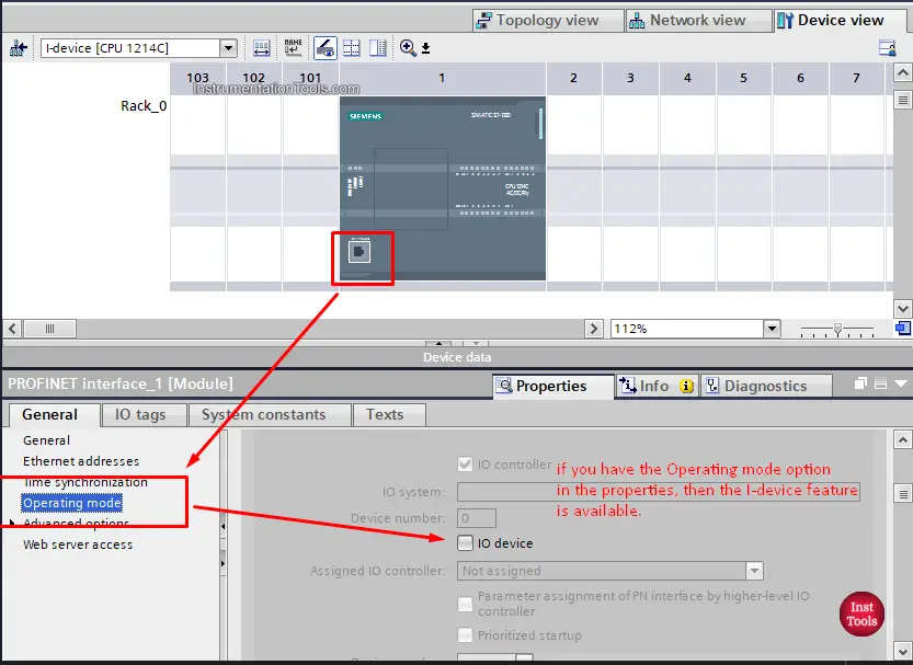
Picture 1b. PLC supports the I-device feature
As you see from the picture, this PLC supports the I-device feature.
A PLC with the “Intelligent IO device” configuration is called an I-Device. An I-Device is like a standard IO device and needs to be handled like one. This means that the I-Device is also connected to a higher-level IO controller.
So , an I-device will act as an IO module, but it is also still a PLC, so it still acts as a controller if you want it to.
Data exchange concept
The guiding principle of the I-Device method is to use the known process image in a CPU. From the higher-level IO controller’s view, communicating to an I-Device is similar to communicating to a distributed IO with the usual read and write processes at inputs and outputs.
From the I-Device’s view, data transfer to a higher-level IO controller is also analog to the data transfer to the local or assigned distributed IO via inputs and outputs.
I-device Configuration options
There are two possibilities for configuration:
- Configuring an I-Device within a project.
- Configuring an I-Device that is used in another project
When configuring an I-Device for another project, STEP 7 enables you to do this by exporting a configured I-Device in a GSD file. The GSD file can be imported in the other project or the other engineering system like other GSD files.
This allows not only for communication within the project, but also communication across projects and data exchange between different manufacturers in a tried and tested way. We will show that in another article.
In this article, we will show the Configuration of the I-device within the same Siemens PLC project.
I-device configuration within the same PLC project
We will assume that we have two PLCs in our project, CPU 1516-3 PN/DP which will act as the controller in this configuration, and CPU 1214C which will act as the I-device.
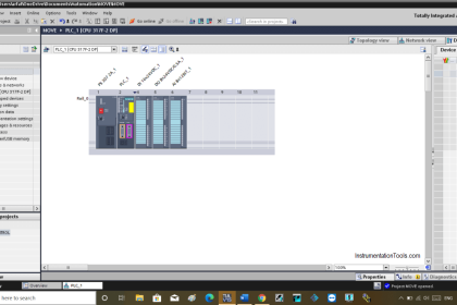
Start by adding the two PLCs into your TIA Portal project and setup a Profinet connection between them. See picture 2.
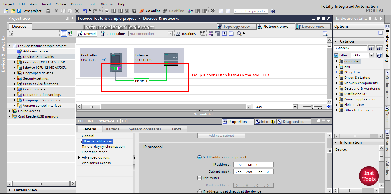
picture 2. Setup connection between two PLCs.
Now, we need to configure the CPU 1214C PLC as an I-device.
You do that by going to the Profinet interface properties and from the operating mode option you click on the IO device option. See picture 3.
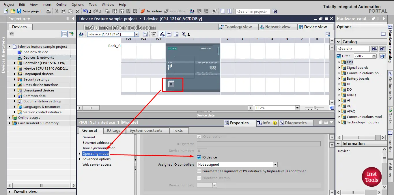
picture 3. Select IO device.
After that, you need to assign the I-device to a higher-level controller which is the CPU 1516-3 PN/DP PLC in our project.
To do that just select that PLC from the Assigned IO controller drop-down list. See picture 4.
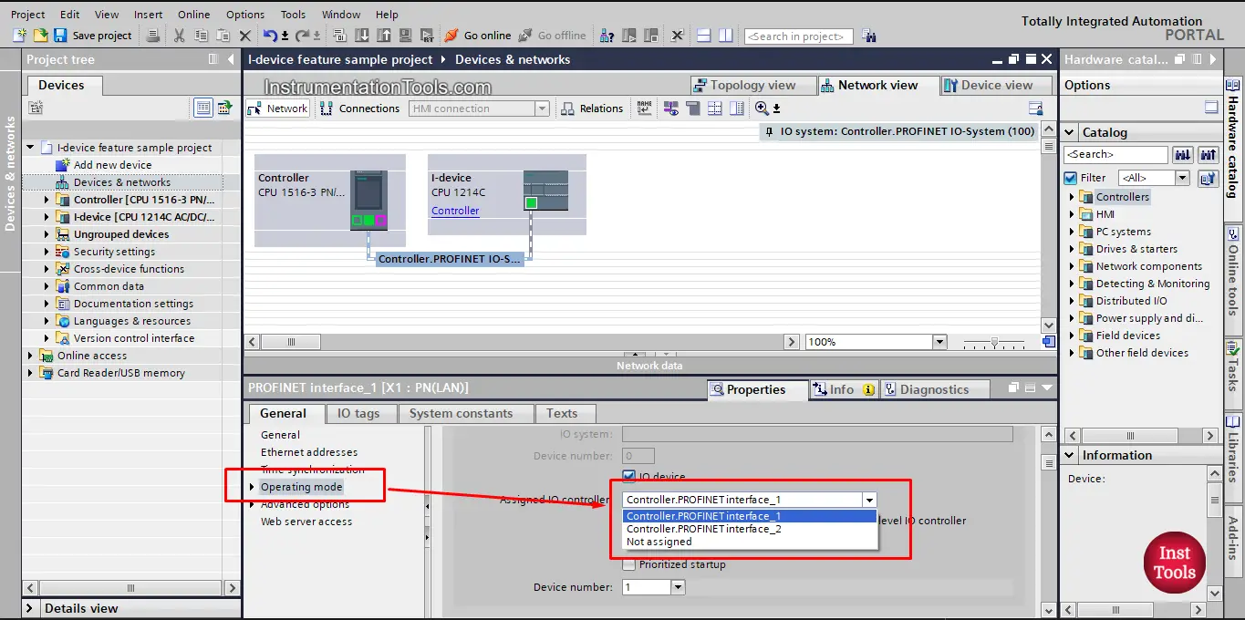
picture 4. Assign the I-device to the controller.
After that, the I-device is now connected and assigned to the controller PLC. See picture 5.
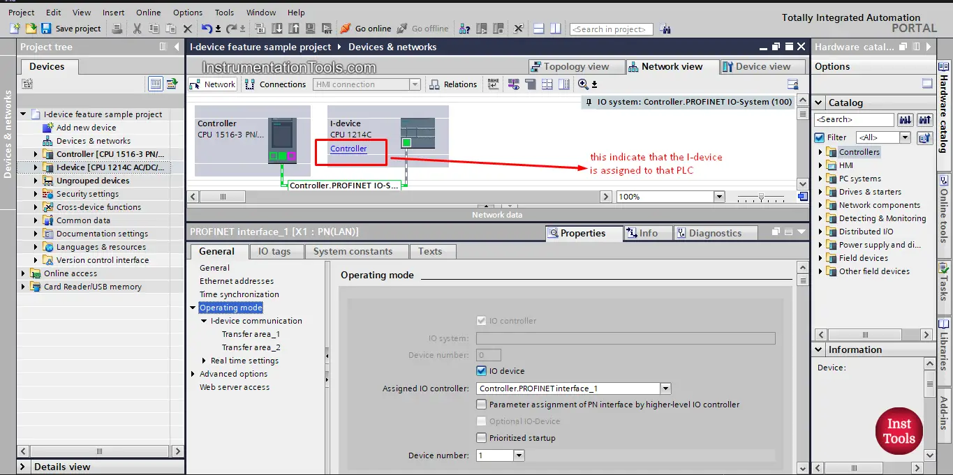
picture 5. The I-device is assigned to the controller PLC.
The next step is to exchange the data between the I-device and the controller with what is known as transfer areas.
Creating a transfer area
Transfer areas are the IO areas that are used to exchange data between the I-Device and the higher-level IO controller.
Go to the “I-Device Communication” section. Click the first field of the “Transfer areas” column. TIA Portal will create a predefined name that you are able to change. As you can see from picture 6.
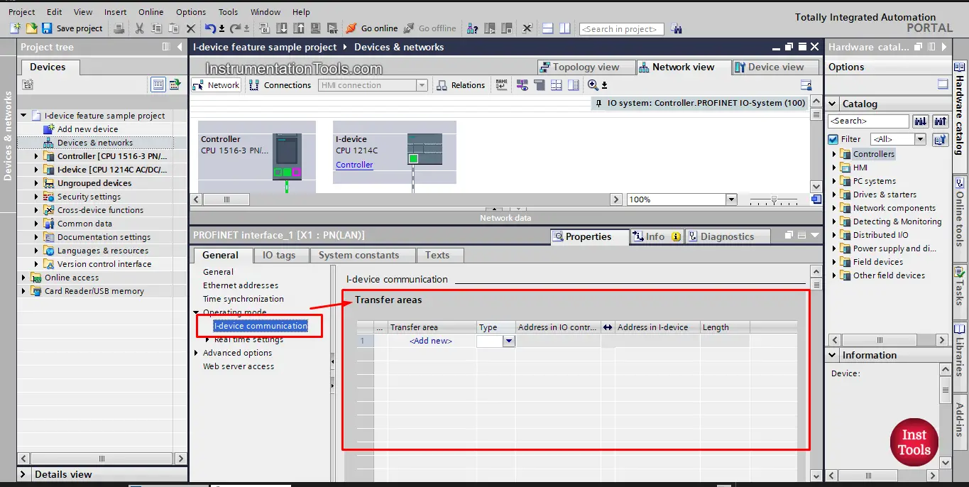
picture 6. Create a transfer area
Select the type of communication relationship: currently, only CD can be selected. See picture 7.
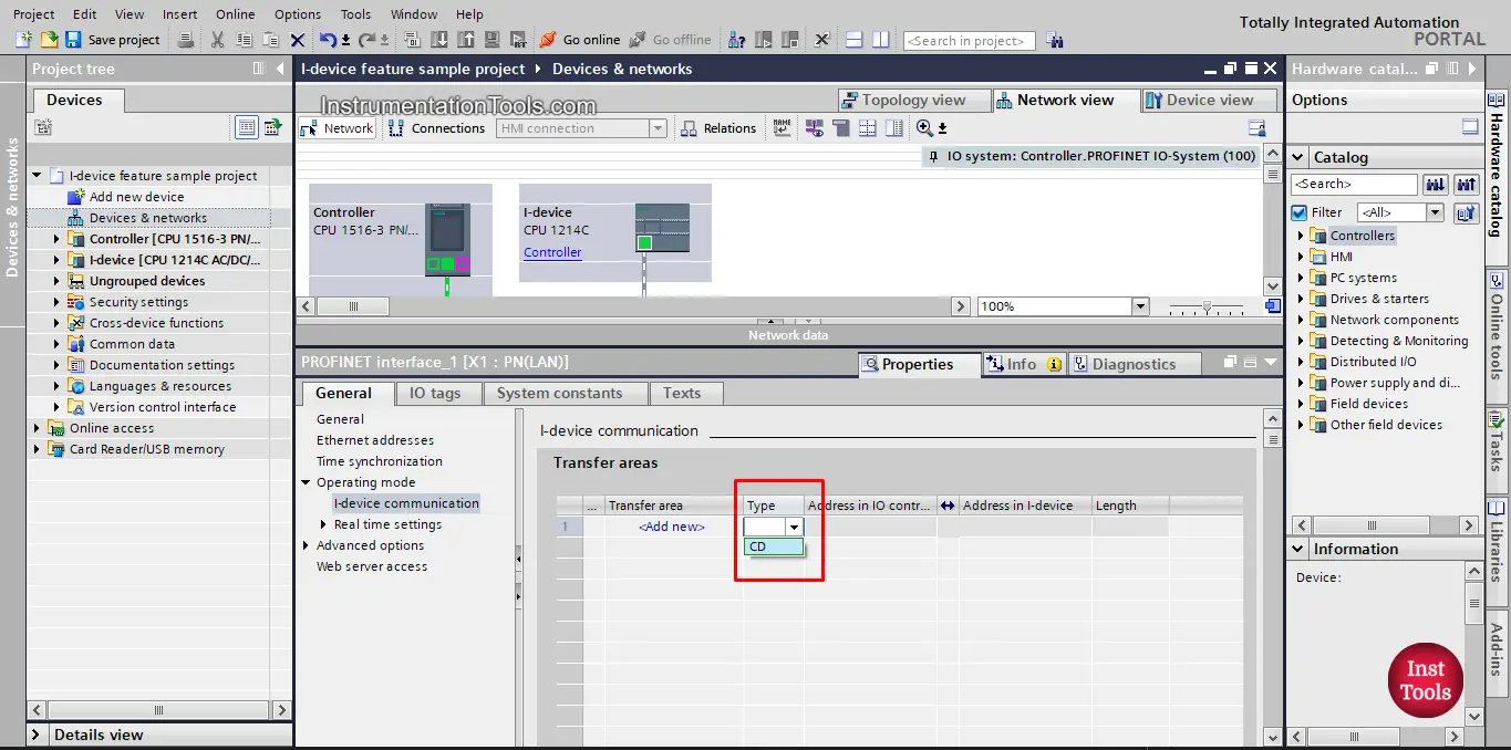
Picture 7. Choose CD communication option.
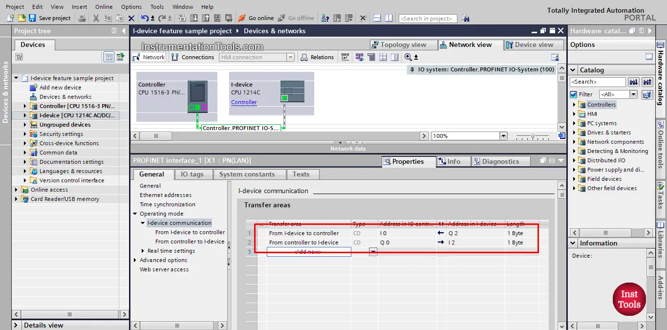
Once you select the CD option, a transfer area will be created and the addresses of the IO controller and I-device will be automatically created. See picture 8.
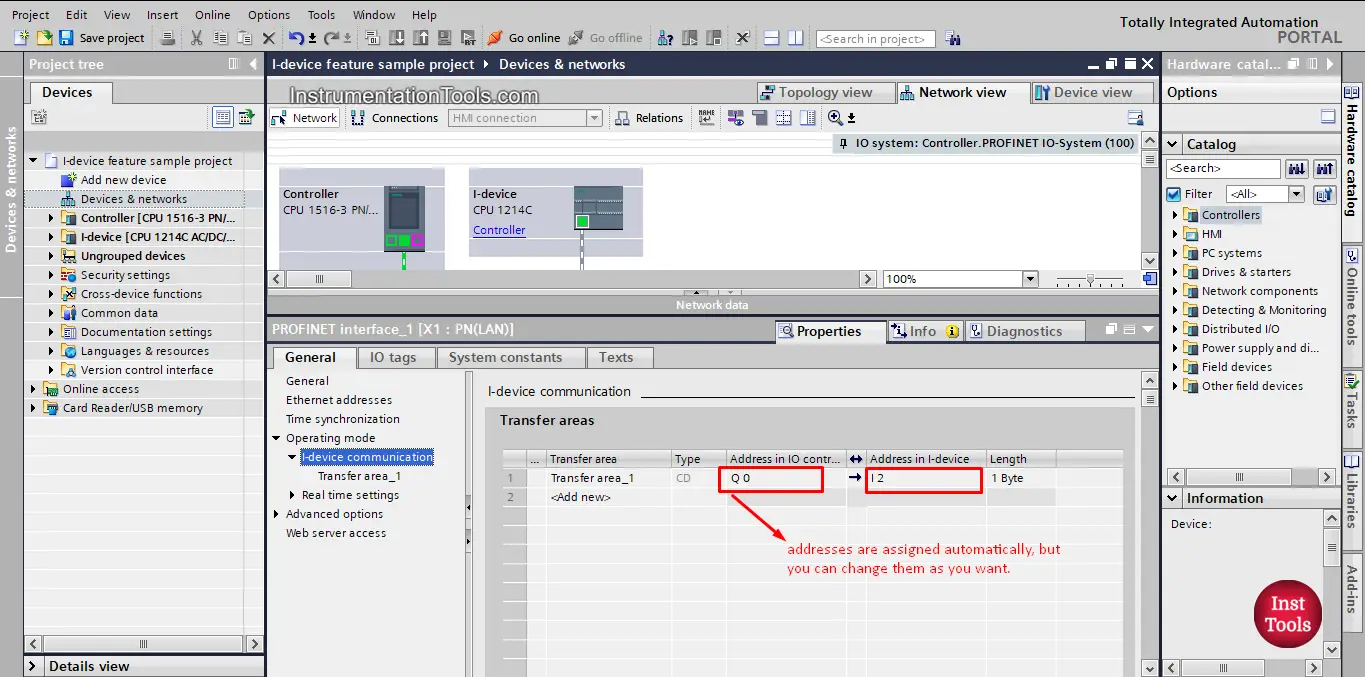
Picture 8. Transfer area is created.
The addresses are pre-assigned automatically, if required, you can adjust the addresses to your environment and specify the length of the transfer area to be transferred consistently.
To create another transfer area as before, just press the “add new”, see picture 9.
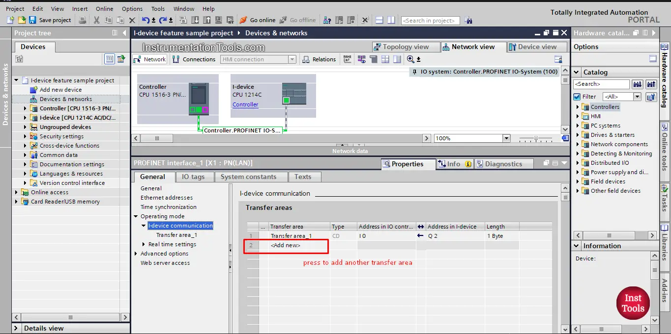
picture 9. Add new transfer area.
As we said before, data exchange is based on the simple processing image concept, which means you always send an output and receive an input.
Also note that the arrow you see in previous picture indicates the flow of information between the I-device and the controller. So if I send data from the controller to the I-device then the arrow will be from the controller to I-device and the address of controller will be output and address of I-device will be input and vise verse as you can see from previous picture.
Also keep in mind that it is always better to rename your transfer areas to proper indicating names. See picture 10.
Picture 10. Rename your transfer areas.
Loading the PLC project
To load the PLC project data, select both controllers one after the other in the project navigation and load the project into the respective module.
Note that, because we don’t have actual hardware devices, we can’t simulate this feature.
Download this PLC project files.
In the next article, we will show another way to communicate and exchange data between two PLCs in the same project or in different projects.
If you liked this article, then please subscribe to our YouTube Channel for Instrumentation, Electrical, PLC, and SCADA video tutorials.
You can also follow us on Facebook and Twitter to receive daily updates.
Read Next:
- Free PLC Training for Students
- S7-1200 Hardware Configuration
- Factory IO and Siemens Tia Portal
- How to Choose a PLC for a Project?
- What is Multi-touch Technology?