Inst ToolsInst ToolsInst Tools
  • Courses
  • Automation
    • PLC
    • Control System
    • Safety System
    • Communication
    • Fire & Gas System
  • Instrumentation
    • Design
    • Pressure
    • Temperature
    • Flow
    • Level
    • Vibration
    • Analyzer
    • Control Valve
    • Switch
    • Calibration
    • Erection & Commissioning
  • Interview
    • Instrumentation
    • Electrical
    • Electronics
    • Practical
  • Q&A
    • Instrumentation
    • Control System
    • Electrical
    • Electronics
    • Analog Electronics
    • Digital Electronics
    • Power Electronics
    • Microprocessor
  • Request
Search
  • Books
  • Software
  • Projects
  • Process
  • Tools
  • Basics
  • Formula
  • Power Plant
  • Root Cause Analysis
  • Electrical Basics
  • Animation
  • Standards
  • 4-20 mA Course
  • Siemens PLC Course
Reading: Schneider Electric PLC Timer Problem: Vacuum Cleaner
Share
Font ResizerAa
Inst ToolsInst Tools
Font ResizerAa
  • Courses
  • Design
  • PLC
  • Interview
  • Control System
Search
  • Courses
  • Automation
    • PLC
    • Control System
    • Safety System
    • Communication
    • Fire & Gas System
  • Instrumentation
    • Design
    • Pressure
    • Temperature
    • Flow
    • Level
    • Vibration
    • Analyzer
    • Control Valve
    • Switch
    • Calibration
    • Erection & Commissioning
  • Interview
    • Instrumentation
    • Electrical
    • Electronics
    • Practical
  • Q&A
    • Instrumentation
    • Control System
    • Electrical
    • Electronics
    • Analog Electronics
    • Digital Electronics
    • Power Electronics
    • Microprocessor
  • Request
Follow US
All rights reserved. Reproduction in whole or in part without written permission is prohibited.
Inst Tools > Blog > PLC Tutorials > Schneider Electric PLC Timer Problem: Vacuum Cleaner

Schneider Electric PLC Timer Problem: Vacuum Cleaner

Find vacuum cleaner solutions to Schneider Electric PLC timer problems with the help of Ecostruxure Machine Expert-Basic software.

Last updated: December 11, 2024 4:18 pm
Editorial Staff
PLC Tutorials
No Comments
Share
7 Min Read
SHARE

This article discusses examples of applying the sequential program concept in the Schneider Ecostruxure Machine Expert-Basic software based on the vacuum cleaner application.

Contents
Schneider Electric PLC Timer ProblemPLC IO DetailsVacuum Cleaner PLC Programming

Schneider Electric PLC Timer Problem

PLC program has 4 buttons, the START_SYSTEM (I0.0) button is used to turn ON the system, the STOP_SYSTEM (I0.1) button is used to turn OFF the system, the SELECTOR_MODE (I0.2) button is used to select the mode to be Run, and the VACUUM_CLEANER_BUTTON (I0.3) is used to turn ON the VACUUM_CLEANER (Q0.0) output when the system is Running in Manual mode.

This PLC system can be Run in 3 modes, Manual, Timer, and Auto. The value in memory word MODE (MW0) will increase (+1) if the SELECTOR_MODE (I0.2) button is Pressed. When the value in memory word MODE (MW0) is equal to “3”, the memory word MODE (MW0) will automatically reset to zero “0” and the system returns to Manual mode.

If the START_SYSTEM (I0.0) button is pressed, the system will be in a Standby state. The system will be OFF if the STOP_SYSTEM (I0.1) button is Pressed.

In sequence-1, the memory word MODE (MW0) will be zero “0” and the system is in “Manual” mode.

In Manual mode, if the VACUUM_CLEANER_BUTTON (I0.3) button is Pressed, the VACUUM_CLEANER (Q0.0) output will be ON.

In sequence 2, the memory word MODE (MW0) will have a value of one “1” and the system is in “Timer” mode. In this Mode, the VACUUM_CLEANER (Q0.0) output will be ON for 4 seconds and will be OFF for 4 seconds. This situation will continue to repeat itself.

In sequence 3, the memory word MODE (MW0) will be two “2” and the system is in “Auto” mode.

In this mode, if the value in memory word DUST_LEVEL (MW1) is Greater Than Or Equal to “30”, then the VACUUM_CLEANER (Q0.0) output will be ON.

PLC IO Details

CommentInput (I)Output (Q)Memory BitsMemory WordTimers
START_SYSTEMI0.0    
STOP_SYSTEMI0.1    
SELECTOR_MODEI0.2    
VACUUM_CLEANER_BUTTONI0.3    
VACUUM_CLEANER Q0.0   
MODE   MW0 
DUST_LEVEL   MW1 
TIMER1    TM0
TIMER2    TM1
SYSTEM_ON  M0  
IR_MANUAL_MODE  M1  
IR_TIMER_MODE  M2  
IR_AUTO_MODE  M3  
IR_TIMER1  M4  
IR_TIMER2  M5  

Vacuum Cleaner PLC Programming

RUNG 0 (SYSTEM ON)

In this Rung, the memory bit SYSTEM_ON (M0) changes to a HIGH state when the START_SYSTEM (I0.0) button is Pressed. The memory bit SYSTEM_ON (M0) remains HIGH even though the START_SYSTEM (I0.0) button has been Released because it uses Latching.

If the STOP_SYSTEM (I0.1) button is Pressed, the memory bit SYSTEM_ON (M0) will become a LOW state.
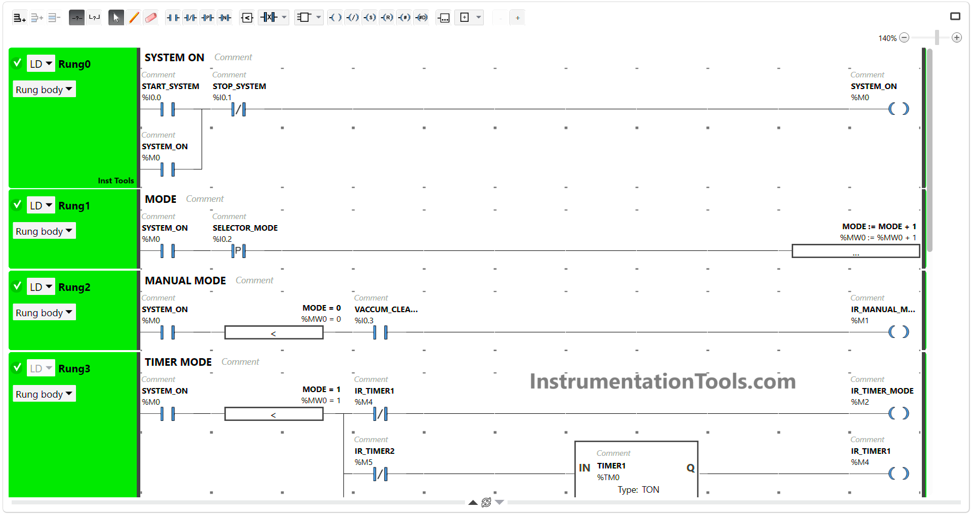
Schneider Electric PLC Timer Problem

RUNG 1 (MODE)

In this Rung, the value in memory word MODE (MW0) will increase (+1), if the NO contact of memory bit SYSTEM_ON (M0) in HIGH state and the SELECTOR_MODE (I0.2) button is Pressed (once).

RUNG 2 (MANUAL MODE)

The memory bit IR_MANUAL_MODE (M1) will change to the HIGH state if the NO contact of memory bit SYSTEM_ON (M0) in the HIGH state and the memory word MODE (MW0) is equal to zero “0” and the VACUUM_CLEANER_BUTTON (I0.3) button is Pressed.
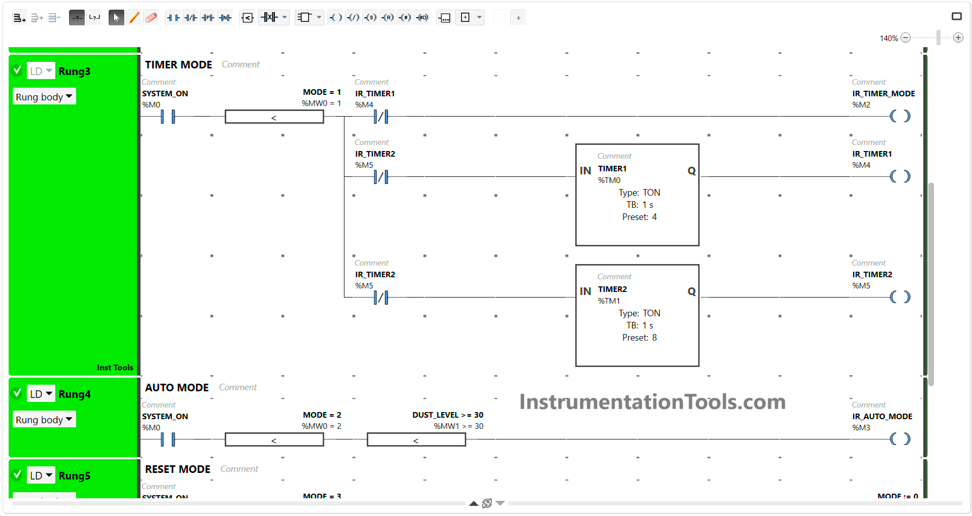
Timer-based vacuum cleaner in Schneider PLC

RUNG 3 (TIMER MODE)

In this Rung, the memory bit IR_TIMER_MODE (M2) will be in the HIGH state, if the NO contact of memory bit SYSTEM_ON (M0) in the HIGH state and the memory word MODE (MW0) is equal to “1”.

The timer instruction TIMER1 (TM0) will Start counting up to 4 seconds and TIMER2 (TM1) will count up to 8 seconds.

When the timer TIMER1 (TM0) finishes counting, the memory bit IR_TIMER1 (M4) becomes a HIGH state and the memory bit IR_TIMER_MODE (M2) changes to a LOW state due to interlock.

When the TIMER2 (TM1) timer finishes counting, the timer TIMER1 (TM0) will be OFF because the interlock of memory bit IR_TIMER2 (M5) and the memory bit IR_TIMER_MODE (M2) will change to HIGH state again.

RUNG 4 (AUTO MODE)

In this Rung, the memory bit IR_AUTO_MODE (M3) will change to HIGH state when the NO contact of memory bit SYSTEM_ON (M0) in HIGH state and the memory word MODE (MW0) has a value Equal to zero “0” and memory word DUST_LEVEL (MW1) has a value Greater Than Or Equal to “30”.
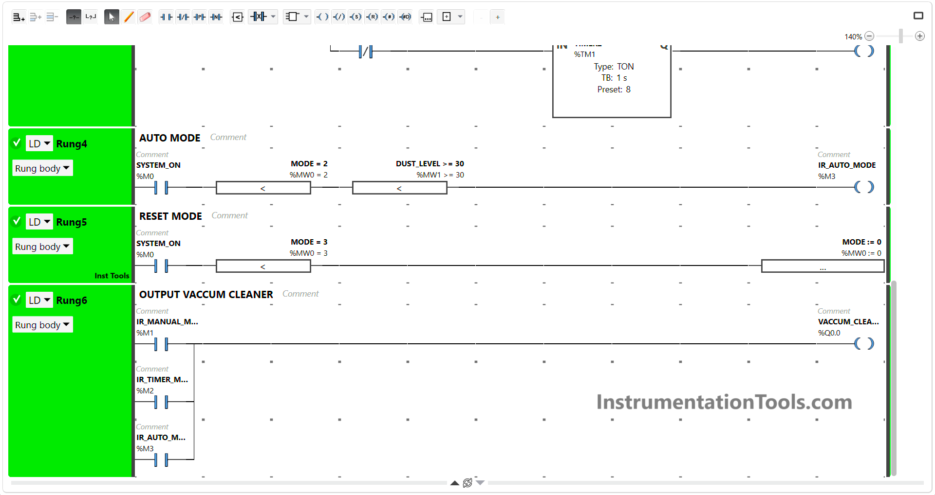
Schneider Electric automatic vacuum cleaner timer

RUNG 5 (RESET MODE)

In this Rung, the Operation Block will move the zero value “0” to the memory word MODE (MW0) when the NO contact of memory bit SYSTEM_ON (M0) in the HIGH state and the memory word MODE (MW0) has a value equal to zero “3”.

RUNG 6 (OUT VACUUM CLEANER)

If the NO contact of the memory bit IR_MANUAL_MODE (M1) or IR_TIMER_MODE (M2) or IR_AUTO_MODE (M3) in the HIGH state, then the VACUUM_CLEANER (Q0.0) Output will be ON.

Read Next:

  • How to do Simulation in Schneider PLC?
  • Automatic Car Washing using the PLC Logic
  • Omron PLC Logic for Washing Machine
  • Configure PID Controller in Schneider PLC
  • Automate Batch Mixing with Repeated Cycle

Don't Miss Our Updates
Be the first to get exclusive content straight to your email.
We promise not to spam you. You can unsubscribe at any time.
Invalid email address
You've successfully subscribed !

Continue Reading

How to Communicate with Excel from Intouch SCADA?
One-Shot Rising and Falling Edge Instructions in Rockwell PLC
ON Delay Timer using PLC
PLC to PLC Communication using S7 Connection PUT & GET Instructions
PLC Analog Input Scaling
PLC Example to Control LEDs Via Switches
Share This Article
Facebook Whatsapp Whatsapp LinkedIn Copy Link
Share
Leave a Comment

Leave a Reply Cancel reply

Your email address will not be published. Required fields are marked *

Stay Connected

128.3kFollowersLike
69.1kFollowersFollow
210kSubscribersSubscribe
38kFollowersFollow

Categories

Explore More

PLC Trainer Demo Download
Procedure for Siemens S7-300 Download from PC to PLC
PLC Program using START and STOP Buttons
Data Types in PLC – Bit, Byte, Integer, Real, String
Schneider Electric: Car Parking System with Calculations in PLC
Structured Text PLC Example for Motor Interlocking and Control
Instrumentation Engineer Activities & Documents – Detail Design Phase
OMRON PLC Math Instructions: +(400), -(410), *(420), /(430)

Keep Learning

SCADA Graphics

What is SCADA ? How does SCADA Works ?

Siemens PLC Device and Network

Difference Between PLCSIM and PLCSIM Advanced? – Siemens PLC

Converter Instruction in Siemens PLC Programming

Converter Instruction in Siemens PLC Programming

Site Acceptance Test (SAT) of PLC System

PLC System Site Acceptance Test (SAT)

PID Setup

PID in Studio 5000

InTouch SCADA Training Course

Free InTouch SCADA Tutorial Course for Beginners

HMI Screen Design for Hazardous Applications

HMI Screen Design for Hazardous Applications

Classification of Fuses

Step-by-Step Guide to Choose Right Fuse for a Panel

Learn More

Top 100 Power Plant Engineering Objective Questions & Answers

Top 100 Power Plant Engineering Objective Questions & Answers

Tank level control system

Determining the Design Purpose of Override Controls

Automating Car Parking with Advanced PLC Logic

Complex Car Parking Logic in XG5000 LS Electric PLC

Rotational Viscometer

What is a Viscometer? – Types, Applications, Advantages

High Integrity Pressure Protection System HIPPS

Overview of HIPPS System

Location of Pressure Taps

Design Considerations of Orifice Plate

Difference between PLC and Computers

Difference between PLC and Computers

SCADA Run

PLC Based Industrial Conveyor Ladder Logic

Menu

  • About
  • Privacy Policy
  • Copyright

Quick Links

  • Learn PLC
  • Helping Hand
  • Part Time Job

YouTube Subscribe

Follow US
All rights reserved. Reproduction in whole or in part without written permission is prohibited.
Welcome Back!

Sign in to your account

Username or Email Address
Password

Lost your password?