Industrial Process Plant Projects are the results of activities and produced documentation for providing packages, equipment, devices, instruments, etc, and making interconnections and interfaces between them (during the installation and construction and following phases) to make an integrated item as a Process Plant to produce our products.
The final success of each industrial process plant project is directly related to the established safety and performance of the process plant. On the other hand, as much as the Process Operation/Logic (for control & safety) is implemented better, the final results of the project will be more successful.
In this article, we will learn the Process Control & Safety Systems logics implementation cycle and operations in industrial plants and projects.
Process Plant Control & Safety Systems Aspects
Before starting our study, let us have an overview of the expected aspects of Process Plant Control & Safety Systems. Figure 1 shows generally the main items of such aspects.
Figure-1: Process Plant Control & Safety Systems Aspects.
In fact during the execution of each Industrial Process Plant Project, by providing documents and doing different activities, some different Control & Safety Systems are installed and configured to make some facilities by which different operational and safety functions are available (as automatic or by human interactions).
Some of the main expected functional facilities (as shown in Figure 1) may include:
- Total Functional Control
- Total Functional Safety
- Unit/ Package Wise Control
- Unit/ Package Wise Safety
- Auto/ Interlock Logics (for making some Automation)
- Safety/ Protection Logics (for establishing different Plant Protection Layers including F&G systems)
- Sequence Controls
- Controllers Settings
- Operator Actions
- Alarm Management
- Data Storage/ Historian (for performance or accident analysis or any comparisons on changes and modifications)
- (Parameters Values/ Status) Monitoring
- Data/ Signals Transfer (Communications) or Networks
- Management Information System (MIS)
- Asset/ Maintenance Management Systems (MMS)
- Production Plan Control
- Internet/ WAN (Enterprise/ Outside Work/ Distributed Plant) …
As Figure 1 shows, the provided documents for reaching the mentioned Control & Safety Systems aspects may be divided into three main targets such as:
- Documents for Installations (Instruments, Systems, and all Auxiliaries or Accessories such as Cables, JBs, Trays/ Ladders, Tubing, …)
- Documents for Systems Implementations (Design and Configurations)
- Documents for Plant Maintenance & Operations (daily plant operations)
In fact, Detail Design (Engineering) documents in the form of specifications, datasheets, lists, texts, drawings, diagrams, and tables,… transfer the Project Design Requirements (Process Control Systems Philosophies) to the required aspects that were expected.
However during Plant Operation & Maintenance phase provided systems can produce some actual documentation (such as reports, loggings, tracings, and print-outs …) too.
Tree Model of Process Control & Safety Systems Operation/ Logics Implementing Cycle
If we consider the implementing cycle of Process Control & Safety Systems as three main (general) steps:
1) Detail Engineering Design,
2) Systems Assembly & Configurations and Installation,
3) Using the Process Control & Safety Systems aspects (Hardware & Software Interfacings) for Operation Facilities, then we can define such implementing cycle as the “Tree Model” shown in Figure 2.

Figure 2: “Tree Model” of Process Plant Control & Safety Systems Operation/ Logics Implementing Cycle.
As Figure-2 shows the Engineering Design (documentation and activities) is the Tree Roots, while the Systems Assembly and Configurations are the Tree Peduncle, and the Interfacing Facilities (Hardware & Software) are the Tree Products (Fruits & Branches).
Simply we can say that if the Tree Roots are strong (and well supplied) and provided based on suitable seed and ground (base) and appropriate conditions we can expect the Tree to have strong Peduncle (Stem) and desirable final products. On the other hand, we can say the Engineering Design (documentation & activities) has the main role in reaching suitable final targets.
Project Data and Documents
In fact, the Project Requirements shall be completely processed to reflect in suitable data and documents for at least the following expectations:
- Client/ End-User Concerns
- Complex Loops Diagrams
- Process/ Logics Descriptions
- Cause & Effects Diagrams
- P&ID’s
- Instrument Index (I/O Lists)
- Process Systems Architecture (Control Systems Block Diagram)
- Signal Interface Lists/ Diagrams
- Systems Specifications (HW + SW + HMI) …
By supplying such expected data and documents, the required functionalities may be available successfully (of course if the following steps are used properly). However as much as the data transfer and implementing functional facilities (Control & Safety Systems aspects) follow the regular procedures and standards, the project success can be achievable more.
As an example if project requirements reflected in ISA5.2 standard format and systems vendors also follow IEC-61131-3 for exact implementations of requirement by standard languages, we may hope to have good success on implementing Logics and Functionality Facilities.
Instrumentation & Control in Process Plant Functional Operation Cycle
Although all project technical teams shall provide the whole Project Requirements exactly and completely, but PROCESS/ HSE and I&C (Instrumentation & Control) Teams have the main roles and responsibilities to transfer Process Functional Requirements to the right and correct Control & Safety Systems aspects.
Figure-3 shows the main I&C Team Roles and Responsibilities during the implementation Process Plant Functional Operation Cycle of an Industrial Project generally (as an overview). As the figure implicitly shows, the I&C Team further to their own activities shall have close coordination and interactions with other parties such as Technical Teams, Vendors (Instruments, Systems, Packages,…), Clients/ End-User
Specialists, Project Management including Procurement and Planning), …
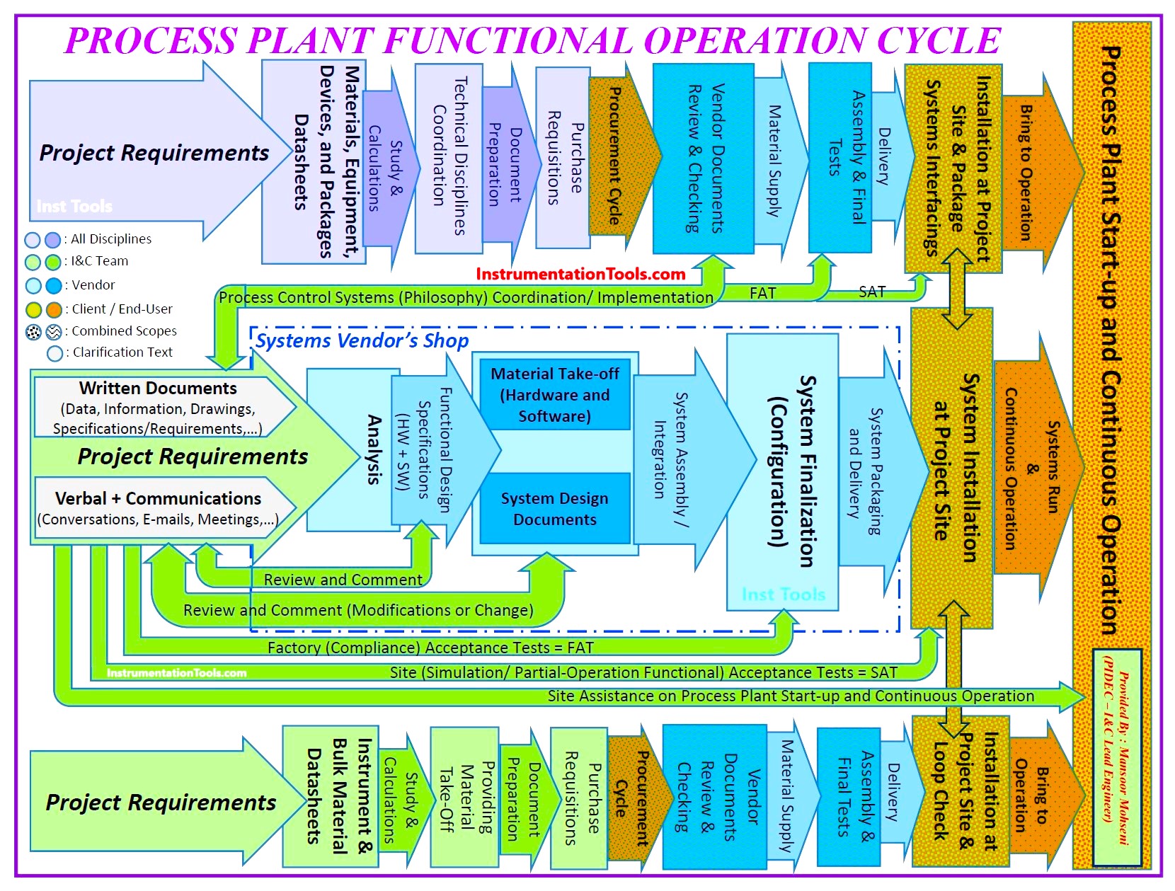
Figure-3: General I&C Roles & Responsibilities during implementing Process Functional Operation Cycle.
Figure-3 shows some more detail on applying Project Requirement Transfers in different steps of Implementing the Process Plant Functional Operation Cycle of an Industrial Project. Especially it shows that further to Written Documents (with some details mentioned above in this article) some Project Requirements shall be transferred in other formats such as Verbal and Human Communications (Conversations, E-mails, Meetings, etc.).
Also we can find that further to establishing System Finalization & Configurations they shall follow for provision of Instruments and relevant Auxiliary Items & Accessories (directly by themselves) and Packages Provision (with interactions to other teams) up to installation at the project site (in parallel plan schedules).
Instrument Engineer
Based on Figure-3 we may define the Instrument & Control engineer Roles & Responsibilities during the Implementing Control & Safety Systems of the Process Plant Functional Operation Cycle as following 7 general steps:
- Providing Detail Design (Engineering) Documents and Data
- Actions in the Procurement Phase, up to Selecting Wined Systems Vendors
- Review and Commenting on Vendor Analysis Outputs (provided HW + SW Functional Design Specifications (FDS)).
- Review and Commenting on Vendor System Design Documents and relevant Material Take-Offs (and asking for any required modifications or changes).
- Compliance Checking by Doing Factory Acceptance Tests (FAT)
- Final Actual Compliance Checking by Doing Site (Simulation/ Partial-Operation Functional) Acceptance Tests (SAT)
- Site Assistance on Process Plant Start-up and Continuous Operation during Hot Running of Control & Safety Systems
During the last two steps, all Process Plant Components and Elements (packages, devices, instruments, etc.) were installed and engaged and interacted with each other to provide Final Project Plant operational facilities.
Usual and Extra (Unusual) Data/ Document Transfer for Implementing Control & Safety Systems
As explained above, the I&C Team shall transfer Project Requirements (based on the Project Control & Safety Systems Philosophy) to systems vendors via proper data and documents. Some of the required functionalities will be done based on usual known procedures (and agreements), while for applying some of the complex items, Systems Vendors need more documents or activities from the I&C Team.
As an example, Systems Vendors know how to use project documents for applying the usual Monitoring and PID Controller Loops, while for implementing Complex Loops they need more help or extra documents or conversations from the I&C Team.
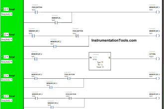
Logics and Interlocks
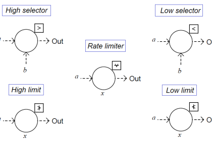
Figure-4 shows some possible (Control or Safety) loops which are usually shown on P&ID documents. Logics and Interlocks shown in this figure may be considered as usual loops too, that systems vendors may implement them by using other project documents (such as Cause & Effects or Process Descriptions or Narratives), while in some Detail Design Engineering companies, I&C Team may provide additional documents as Design Standard Logics/ Interlocks Diagrams (based on ISA5.2) and it may facilitate and increase the accuracy of implemented Logics/ Interlocks by vendors (based on standard languages of IEC 61131-3).
For implementing other functional controls such as Sequential Control or Complex calculations and decision-making (such as Advanced Process Control (APC)), they need surely extra documents or drawings from pthe roject I&C-Team. It is clear that company practices and I&C Team abilities & skills will have great factors for transferring right and complete expected control functionalities.
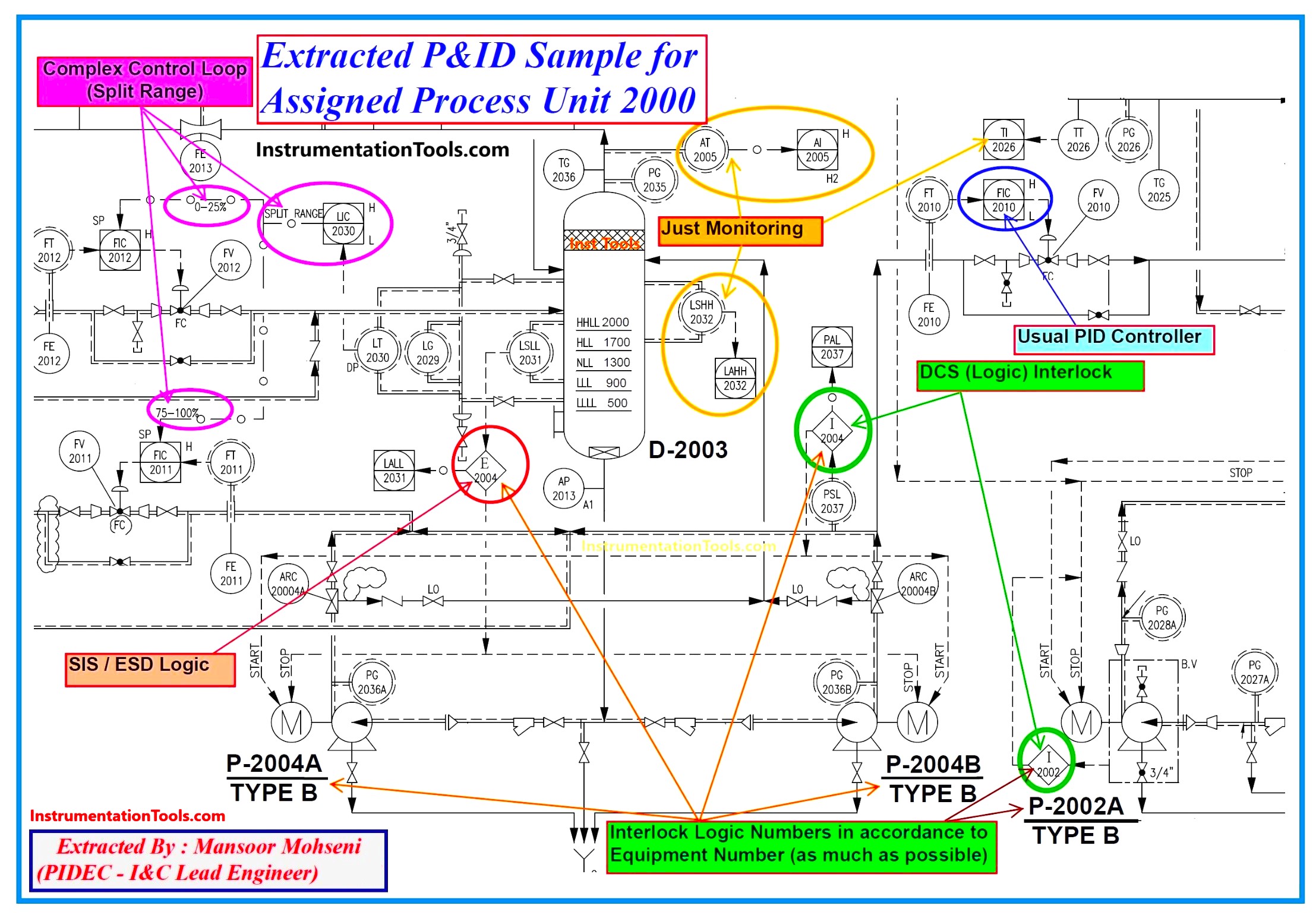
Figure-4: Sample of extracted P&ID for showing different Control & Safety Systems Functionalities.
Some Advice for Better Implementing Interlock/ Logics
Referring to Figure-4, we try to mention some advice for better implementing Interlock/ Logics in the Process Plant Industrial Project below:
1) Use the same standard symbols indication in developing all Process Plant P&ID’s.
2) Consider Unique Tag Numbers for all Equipment and Instruments that exist in all P&IDs.
3) Consider all Equipment and Instruments in each Process Unit with common parts in Tag Numbers (in accordance with Process Unit assignment).
4) Use the same numbers in assigning Tag Numbers for all accessories to each Equipment and Instrument (as much as possible). As an example use the same numbers in assigning Tag Numbers for Valve and relevant command signals and its open/ close status limit switches and their monitoring.
5) Make complete and exact care in specifying Analog and Digital Signals or Instruments (especially in producing Alarm Signals) in developing P&IDs.
6) Use suitable standard symbol indications for exactly clarifying the existing control and safety systems (DCS/ ESD/ PLC/…).
7) Make complete and exact care in specifying Hardware and Serial Link Signal Line indications on P&IDs.
8) Consider suitable Interlock/ Logic Tag Numbers relevant to Target Systems (as an example you may consider “I” for DCS, “E” or “IS” for ESD/ SIS, and “K”, ”U”, “KS”, “US” for PLC or extra controller system Logics)
9) Consider Interlock Logic Numbers in accordance to Equipment/ Package Number (as much as possible) while keeping separation between different defined Interlock Logic Numbers by some tricks (Please notice that in each Process Unit, you may have different equipment or Packages with same numbers while they have different identifiers (and so different Tag Numbers), and hence you cannot use similar Interlock Logic Numbers, unless if you merge them to consider implementing one Interlock Logic Number for all relevant Equipment and Packages in that Process Unit or separate them by additional distinctions).
10) All shown connected signals to each Interlock Logic Number shall be defined (for required action) in Cause & Effects and/ or Process Description Documents, and vice versa.
11) All internal signal interfaces between different interlock Logic Numbers of the same system shall be shown once on P&IDs.
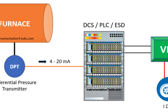
12) The signal interfaces between different systems (Interlock Logics) shall be defined by Unique Tag Numbers and to be shown on P&IDs. As an example, the signal output from ESD/ SIS and input to DCS for forcing some controllers to Manual Mode (on the case) shall be defined with tag numbers and to be shown on P&ID too. See Figure-5.
13) All dedicated action switches (Selectors, Process Override, Start-Up Override, …) shall be defined by tag numbers and shown on P&ID accordingly. (General switches like Maintenance Override Switches are excluded from this item since they can be defined generally by some notes and rules).
14) The relevant Alarm Switch action of each Analog Signals shall be shown exactly and connected to assigned Interlock Logic Numbers, and to be defined exactly in Cause & Effects and/ or Process Description Documents accordingly (for relevant actions).
Such bits of advice are applicable to Process/Safety and I&C Teams of Detail Design Engineering Companies (by close coordination between them) and are reflected in Figure-6.
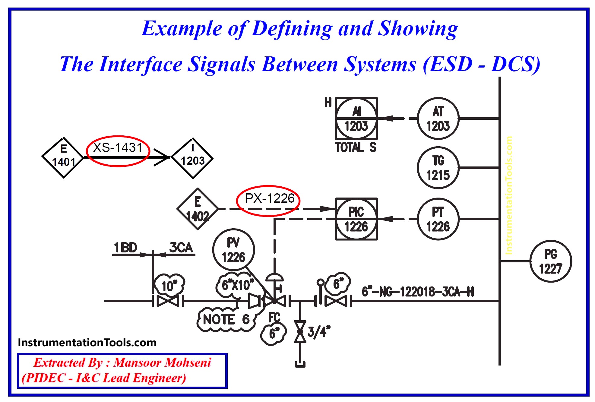
Figure-5: Example of Defining and Showing the Interface Signals Between Systems (ESD – DCS).
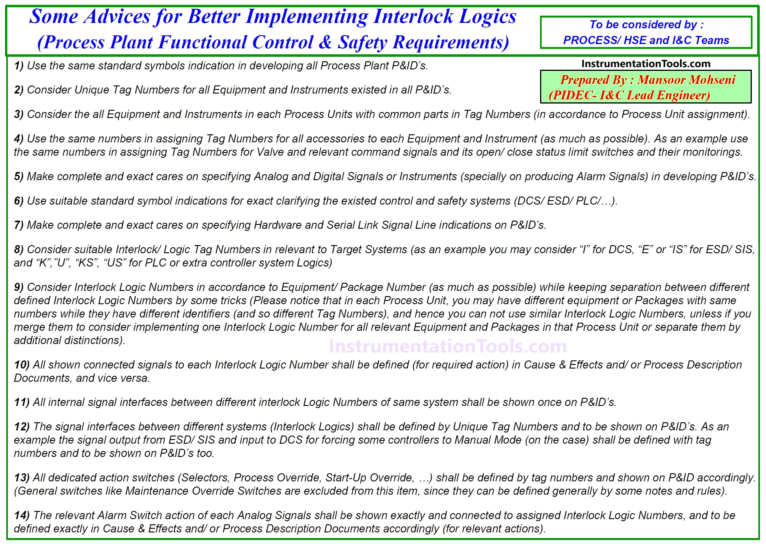
Figure-6: Some Advice for Better Implementing Interlock Logics (Process Plant Functional Control & Safety Requirements).
Complementary Data/ Drawings/ Documents for Project Packages
As Figure-3 shows the I&C Team shall have exact coordination with package Vendors for applying right functional facilities by themselves (their systems) and on the interfaces with Process Control & Safety Systems. The approaches and the required materials for such coordination come from considered Process Control & Safety Systems Philosophy (has been clarified and explained by some articles at Instrumentationtools.com).
Some Process Packages have more complex functionalities than others, and so they may need some more checking and caring on additional data, drawings (and diagrams), and documents further to usual documentation for implementing Control & Safety System facilities.
Figure-7 shows an additional diagram provided by the vendor for implementing the Control & Safety Systems of one Process Package (Turbo-Compressor). As it is clear from the figure, it includes the usage of different calculations and functional blocks for implementing complex facilities. Such a diagram shall be checked by the I&C Team for making comments on modifying or changing some functionalities based on Project Requirements, or adding some extra information and texts for better definition or complete explanation clarifications on used blocks functionalities (document comprehensiveness).
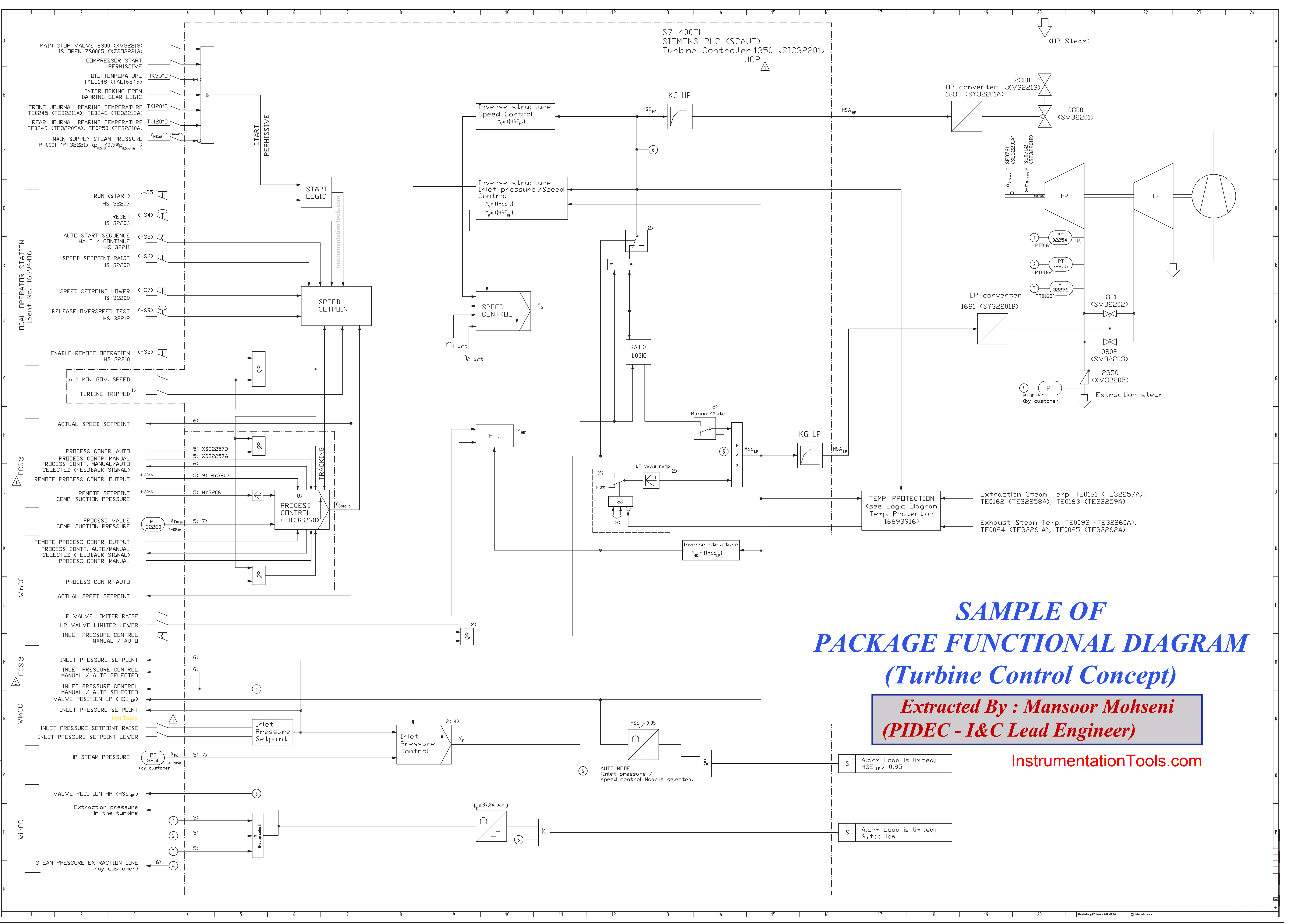
Figure-7: Sample of Package Functional Diagram (Turbine Control Concept).
Figure-8 shows an additional Timing Diagram provided/ developed by the vendor based on project conditions (which is also an extra document). The interpretation of such diagram based on Project Requirements (and conditions) and checking for right mentioned data shall be done by the I&C Team.
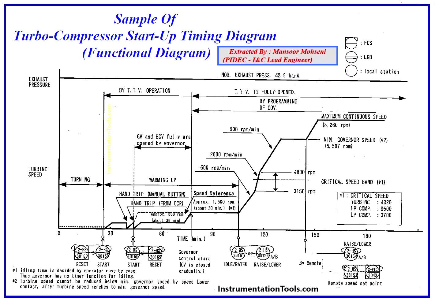
Figure-8: Sample of Turbo-Compressor Stat-up Timing Diagram (Functional Diagram).
During Detail Design Engineering, I&C-Team shall have close coordination with responsible teams (Process/ Safety and Rotary Equipment Teams and Client (Consultants/ Operation) Specialists, further to vendor responsible specialists) to check and finalize such additional documents, and also supervise/ inspect the right implementation (compliance) of such functionalities in Control & Safety Systems (during FAT and SAT).
References:
- Instrument Engineer Roles & Responsibilities
- Instrumentation Engineer Detail Design Phase
- Process Control Systems Philosophy Concepts
- Interaction With Process Control Systems Philosophy


Good for logis procedure
valid
very impressive and well understandable,
no comment well ok
hi ,I am starting to work with SCADA on the 16th march 2025 ,so I need an insight of how it works .I work in lubricants manufacturing(engine ,motor ,hydraulic oils). I want at least 3 courses that will be of essence in this line of work.